ZHCSBT2G November   2012  – October 2017 66AK2H06 , 66AK2H12 , 66AK2H14

PRODUCTION DATA.  

  1. 器件概述
    1. 1.1 特性
    2. 1.2 应用
    3. 1.3 说明
      1. 1.3.1 KeyStone II 的增强功能
    4. 1.4 功能方框图
  2. 修订历史记录
  3. Device Comparison
    1. 3.1 Related Products
  4. Terminal Configuration and Functions
    1. 4.1 Package Terminals
    2. 4.2 Pin Map
    3. 4.3 Terminal Functions
    4. 4.4 Pullup/Pulldown Resistors
  5. Specifications
    1. 5.1 Absolute Maximum Ratings
    2. 5.2 ESD Ratings
    3. 5.3 Recommended Operating Conditions
    4. 5.4 Power Consumption Summary
    5. 5.5 Electrical Characteristics
    6. 5.6 Thermal Resistance Characteristics for PBGA Package [AAW]
    7. 5.7 Power Supply to Peripheral I/O Mapping
  6. C66x CorePac
    1. 6.1 C66x DSP CorePac
    2. 6.2 Memory Architecture
      1. 6.2.1 L1P Memory
      2. 6.2.2 L1D Memory
      3. 6.2.3 L2 Memory
      4. 6.2.4 Multicore Shared Memory SRAM
      5. 6.2.5 L3 Memory
    3. 6.3 Memory Protection
    4. 6.4 Bandwidth Management
    5. 6.5 Power-Down Control
    6. 6.6 C66x CorePac Revision
      1. Table 6-2 CorePac Revision ID Register (MM_REVID) Field Descriptions
    7. 6.7 C66x CorePac Register Descriptions
  7. ARM CorePac
    1. 7.1 Features
    2. 7.2 System Integration
    3. 7.3 ARM Cortex-A15 Processor
      1. 7.3.1 Overview
      2. 7.3.2 Features
      3. 7.3.3 ARM Interrupt Controller
      4. 7.3.4 Endianess
    4. 7.4 CFG Connection
    5. 7.5 Main TeraNet Connection
    6. 7.6 Clocking and Reset
      1. 7.6.1 Clocking
      2. 7.6.2 Reset
  8. Memory, Interrupts, and EDMA for 66AK2Hxx
    1. 8.1 Memory Map Summary for 66AK2Hxx
    2. 8.2 Memory Protection Unit (MPU) for 66AK2Hxx
      1. 8.2.1 MPU Registers
        1. 8.2.1.1 MPU Register Map
        2. 8.2.1.2 Device-Specific MPU Registers
          1. 8.2.1.2.1 Configuration Register (CONFIG)
            1. Table 8-9 Configuration Register Field Descriptions
      2. 8.2.2 MPU Programmable Range Registers
        1. 8.2.2.1 Programmable Range n Start Address Register (PROGn_MPSAR)
          1. Table 8-10 Programmable Range n Start Address Register Field Descriptions
        2. 8.2.2.2 Programmable Range n - End Address Register (PROGn_MPEAR)
          1. Table 8-14 Programmable Range n End Address Register Field Descriptions
        3. 8.2.2.3 Programmable Range n Memory Protection Page Attribute Register (PROGn_MPPAR)
          1. Table 8-18 Programmable Range n Memory Protection Page Attribute Register Field Descriptions
    3. 8.3 Interrupts for 66AK2Hxx
      1. 8.3.1 Interrupt Sources and Interrupt Controller
      2. 8.3.2 CIC Registers
        1. 8.3.2.1 CIC0 Register Map
        2. 8.3.2.2 CIC1 Register Map
        3. 8.3.2.3 CIC2 Register Map
      3. 8.3.3 Inter-Processor Register Map
      4. 8.3.4 NMI and LRESET
    4. 8.4 Enhanced Direct Memory Access (EDMA3) Controller for 66AK2Hxx
      1. 8.4.1 EDMA3 Device-Specific Information
      2. 8.4.2 EDMA3 Channel Controller Configuration
      3. 8.4.3 EDMA3 Transfer Controller Configuration
      4. 8.4.4 EDMA3 Channel Synchronization Events
  9. System Interconnect
    1. 9.1 Internal Buses and Switch Fabrics
    2. 9.2 Switch Fabric Connections Matrix - Data Space
    3. 9.3 TeraNet Switch Fabric Connections Matrix - Configuration Space
    4. 9.4 Bus Priorities
  10. 10Device Boot and Configuration
    1. 10.1 Device Boot
      1. 10.1.1 Boot Sequence
      2. 10.1.2 Boot Modes Supported
        1. 10.1.2.1 Boot Device Field
          1. Table 10-3 Boot Mode Pins: Boot Device Values
        2. 10.1.2.2 Device Configuration Field
          1. 10.1.2.2.1 Sleep Boot Mode Configuration
            1. Table 10-4 Sleep Boot Configuration Field Descriptions
          2. 10.1.2.2.2 I2C Boot Device Configuration
            1. 10.1.2.2.2.1 I2C Passive Mode
              1. Table 10-5 I2C Passive Mode Device Configuration Field Descriptions
            2. 10.1.2.2.2.2 I2C Master Mode
              1. Table 10-6 I2C Master Mode Device Configuration Field Descriptions
          3. 10.1.2.2.3 SPI Boot Device Configuration
            1. Table 10-7 SPI Device Configuration Field Descriptions
          4. 10.1.2.2.4 EMIF Boot Device Configuration
            1. Table 10-8 EMIF Boot Device Configuration Field Descriptions
          5. 10.1.2.2.5 NAND Boot Device Configuration
            1. Table 10-9 NAND Boot Device Configuration Field Descriptions
        3. 10.1.2.3 Serial Rapid I/O Boot Device Configuration
          1. Table 10-10 Serial Rapid I/O Boot Device Configuration Field Descriptions
        4. 10.1.2.4 Ethernet (SGMII) Boot Device Configuration
          1. Table 10-11 Ethernet (SGMII) Boot Device Configuration Field Descriptions
          2. 10.1.2.4.1   PCIe Boot Device Configuration
            1. Table 10-12 PCIe Boot Device Configuration Field Descriptions
          3. 10.1.2.4.2   HyperLink Boot Device Configuration
            1. Table 10-14 HyperLink Boot Device Configuration Field Descriptions
          4. 10.1.2.4.3   UART Boot Device Configuration
            1. Table 10-15 UART Boot Configuration Field Descriptions
        5. 10.1.2.5 Boot Parameter Table
          1. 10.1.2.5.1  EMIF16 Boot Parameter Table
          2. 10.1.2.5.2  SRIO Boot Parameter Table
          3. 10.1.2.5.3  Ethernet Boot Parameter Table
          4. 10.1.2.5.4  PCIe Boot Parameter Table
          5. 10.1.2.5.5  I2C Boot Parameter Table
          6. 10.1.2.5.6  SPI Boot Parameter Table
          7. 10.1.2.5.7  HyperLink Boot Parameter Table
          8. 10.1.2.5.8  UART Boot Parameter Table
          9. 10.1.2.5.9  NAND Boot Parameter Table
          10. 10.1.2.5.10 DDR3 Configuration Table
        6. 10.1.2.6 Second-Level Bootloaders
      3. 10.1.3 SoC Security
      4. 10.1.4 System PLL Settings
        1. 10.1.4.1 ARM CorePac System PLL Settings
    2. 10.2 Device Configuration
      1. 10.2.1 Device Configuration at Device Reset
      2. 10.2.2 Peripheral Selection After Device Reset
      3. 10.2.3 Device State Control Registers
        1. 10.2.3.1  Device Status (DEVSTAT) Register
          1. Table 10-31 Device Status Register Field Descriptions
        2. 10.2.3.2  Device Configuration Register
          1. Table 10-32 Device Configuration Register Field Descriptions
        3. 10.2.3.3  JTAG ID (JTAGID) Register Description
          1. Table 10-33 JTAG ID Register Field Descriptions
        4. 10.2.3.4  Kicker Mechanism (KICK0 and KICK1) Register
        5. 10.2.3.5  DSP Boot Address Register (DSP_BOOT_ADDRn)
          1. Table 10-1 DSP BOOT Address Register (DSP_BOOT_ADDRn)
        6. 10.2.3.6  LRESETNMI PIN Status (LRSTNMIPINSTAT) Register
          1. Table 10-35 LRESETNMI PIN Status Register Field Descriptions
        7. 10.2.3.7  LRESETNMI PIN Status Clear (LRSTNMIPINSTAT_CLR) Register
          1. Table 10-36 LRESETNMI PIN Status Clear Register Field Descriptions
        8. 10.2.3.8  Reset Status (RESET_STAT) Register
          1. Table 10-37 Reset Status Register Field Descriptions
        9. 10.2.3.9  Reset Status Clear (RESET_STAT_CLR) Register
          1. Table 10-38 Reset Status Clear Register Field Descriptions
        10. 10.2.3.10 Boot Complete (BOOTCOMPLETE) Register
          1. Table 10-39 Boot Complete Register Field Descriptions
        11. 10.2.3.11 Power State Control (PWRSTATECTL) Register
          1. Table 10-40 Power State Control Register Field Descriptions
        12. 10.2.3.12 NMI Event Generation to C66x CorePac (NMIGRx) Register
          1. Table 10-41 NMI Generation Register Field Descriptions
        13. 10.2.3.13 IPC Generation (IPCGRx) Registers
          1. Table 10-42 IPC Generation Registers Field Descriptions
        14. 10.2.3.14 IPC Acknowledgment (IPCARx) Registers
          1. Table 10-43 IPC Acknowledgment Registers Field Descriptions
        15. 10.2.3.15 IPC Generation Host (IPCGRH) Register
          1. Table 10-44 IPC Generation Registers Field Descriptions
        16. 10.2.3.16 IPC Acknowledgment Host (IPCARH) Register
          1. Table 10-45 IPC Acknowledgment Register Field Descriptions
        17. 10.2.3.17 Timer Input Selection Register (TINPSEL)
          1. Table 10-46 Timer Input Selection Field Description
        18. 10.2.3.18 Timer Output Selection Register (TOUTPSEL)
          1. Table 10-47 Timer Output Selection Register Field Descriptions
        19. 10.2.3.19 Reset Mux (RSTMUXx) Register
          1. Table 10-48 Reset Mux Register Field Descriptions
        20. 10.2.3.20 Device Speed (DEVSPEED) Register
          1. Table 10-49 Device Speed Register Field Descriptions
        21. 10.2.3.21 ARM Endian Configuration Register 0 (ARMENDIAN_CFGr_0), r=0..7
          1. Table 10-50 ARM Endian Configuration Register 0 Field Descriptions
        22. 10.2.3.22 ARM Endian Configuration Register 1 (ARMENDIAN_CFGr_1), r=0..7
          1. Table 10-51 ARM Endian Configuration Register 1 Field Descriptions
        23. 10.2.3.23 ARM Endian Configuration Register 2 (ARMENDIAN_CFGr_2), r=0..7
          1. Table 10-52 ARM Endian Configuration Register 2 Field Descriptions
        24. 10.2.3.24 Chip Miscellaneous Control (CHIP_MISC_CTL0) Register
          1. Table 10-53 Chip Miscellaneous Control Register Field Descriptions
        25. 10.2.3.25 Chip Miscellaneous Control (CHIP_MISC_CTL1) Register
          1. Table 10-54 Chip Miscellaneous Control Register Field Descriptions
        26. 10.2.3.26 System Endian Status Register (SYSENDSTAT)
          1. Table 10-55 System Endian Status Register Field Descriptions
        27. 10.2.3.27 SYNECLK_PINCTL Register
          1. Table 10-56 SYNECLK_PINCTL Register Field Descriptions
        28. 10.2.3.28 USB PHY Control (USB_PHY_CTLx) Registers
          1. Table 10-57 USB_PHY_CTL0 Register Field Descriptions
          2. Table 10-58 USB_PHY_CTL1 Register Field Descriptions
          3. Table 10-59 USB_PHY_CTL2 Register Field Descriptions
          4. Table 10-60 USB_PHY_CTL3 Register Field Descriptions
          5. Table 10-61 USB_PHY_CTL4 Register Field Descriptions
          6. Table 10-62 USB_PHY_CTL5 Register Field Descriptions
  11. 1166AK2Hxx Peripheral Information
    1. 11.1  Recommended Clock and Control Signal Transition Behavior
    2. 11.2  Power Supplies
      1. 11.2.1 Power-Up Sequencing
        1. 11.2.1.1 Core-Before-IO Power Sequencing
        2. 11.2.1.2 IO-Before-Core Power Sequencing
        3. 11.2.1.3 Prolonged Resets
        4. 11.2.1.4 Clocking During Power Sequencing
      2. 11.2.2 Power-Down Sequence
      3. 11.2.3 Power Supply Decoupling and Bulk Capacitor
      4. 11.2.4 SmartReflex
        1. Table 11-5 SmartReflex 4-Pin 6-bit VID Interface Switching Characteristics
    3. 11.3  Power Sleep Controller (PSC)
      1. 11.3.1 Power Domains
      2. 11.3.2 Clock Domains
      3. 11.3.3 PSC Register Memory Map
    4. 11.4  Reset Controller
      1. 11.4.1 Power-on Reset
      2. 11.4.2 Hard Reset
      3. 11.4.3 Soft Reset
      4. 11.4.4 Local Reset
      5. 11.4.5 ARM CorePac Reset
      6. 11.4.6 Reset Priority
      7. 11.4.7 Reset Controller Register
      8. 11.4.8 Reset Electrical Data and Timing
        1. Table 11-10 Reset Timing Requirements
        2. Table 11-11 Reset Switching Characteristics
        3. Table 11-12 Boot Configuration Timing Requirements
    5. 11.5  Main PLL, ARM PLL, DDR3A PLL, DDR3B PLL, PASS PLL and the PLL Controllers
      1. 11.5.1 Main PLL Controller Device-Specific Information
        1. 11.5.1.1 Internal Clocks and Maximum Operating Frequencies
        2. 11.5.1.2 Local Clock Dividers
        3. 11.5.1.3 Module Clock Input
        4. 11.5.1.4 Main PLL Controller Operating Modes
        5. 11.5.1.5 Main PLL Stabilization, Lock, and Reset Times
      2. 11.5.2 PLL Controller Memory Map
        1. 11.5.2.1 PLL Secondary Control Register (SECCTL)
          1. Table 11-16 PLL Secondary Control Register Field Descriptions
        2. 11.5.2.2 PLL Controller Divider Register (PLLDIV3 and PLLDIV4)
          1. Table 11-17 PLL Controller Divider Register Field Descriptions
        3. 11.5.2.3 PLL Controller Clock Align Control Register (ALNCTL)
          1. Table 11-18 PLL Controller Clock Align Control Register Field Descriptions
        4. 11.5.2.4 PLLDIV Divider Ratio Change Status Register (DCHANGE)
          1. Table 11-19 PLLDIV Divider Ratio Change Status Register Field Descriptions
        5. 11.5.2.5 SYSCLK Status Register (SYSTAT)
          1. Table 11-20 SYSCLK Status Register Field Descriptions
        6. 11.5.2.6 Reset Type Status Register (RSTYPE)
          1. Table 11-21 Reset Type Status Register Field Descriptions
        7. 11.5.2.7 Reset Control Register (RSTCTRL)
          1. Table 11-22 Reset Control Register Field Descriptions
        8. 11.5.2.8 Reset Configuration Register (RSTCFG)
          1. Table 11-23 Reset Configuration Register Field Descriptions
        9. 11.5.2.9 Reset Isolation Register (RSISO)
          1. Table 11-24 Reset Isolation Register Field Descriptions
      3. 11.5.3 Main PLL Control Registers
        1. Table 11-25 Main PLL Control Register 0 (MAINPLLCTL0) Field Descriptions
        2. Table 11-26 Main PLL Control Register 1 (MAINPLLCTL1) Field Descriptions
      4. 11.5.4 ARM PLL Control Registers
        1. Table 11-27 ARM PLL Control Register 0 Field Descriptions
        2. Table 11-28 ARM PLL Control Register 1 Field Descriptions
      5. 11.5.5 Main PLL Controller, ARM, SRIO, HyperLink, PCIe, USB Clock Input Electrical Data and Timing
        1. Table 11-29 Main PLL Controller, ARM, SRIO, HyperLink, PCIe, USB Clock Input Timing Requirements
    6. 11.6  DDR3A PLL and DDR3B PLL
      1. 11.6.1 DDR3A PLL and DDR3B PLL Control Registers
        1. Table 11-30 DDR3A PLL and DDR3B PLL Control Register 0 Field Descriptions
        2. Table 11-31 DDR3A PLL and DDR3B PLL Control Register 1 Field Descriptions
      2. 11.6.2 DDR3A PLL and DDR3B PLL Device-Specific Information
      3. 11.6.3 DDR3 PLL Input Clock Electrical Data and Timing
        1. Table 11-32 DDR3 PLL DDRCLK(N|P) Timing Requirements
    7. 11.7  PASS PLL
      1. 11.7.1 PASS PLL Local Clock Dividers
      2. 11.7.2 PASS PLL Control Registers
        1. Table 11-33 PASS PLL Control Register 0 Field Descriptions (PASSPLLCTL0)
        2. Table 11-34 PASS PLL Control Register 1 Field Descriptions (PASSPLLCTL1)
      3. 11.7.3 PASS PLL Device-Specific Information
      4. 11.7.4 PASS PLL Input Clock Electrical Data and Timing
        1. Table 11-35 PASS PLL Timing Requirements
    8. 11.8  External Interrupts
      1. 11.8.1 External Interrupts Electrical Data and Timing
        1. Table 11-36 NMI and LRESET Timing Requirements
    9. 11.9  DDR3A and DDR3B Memory Controllers
      1. 11.9.1 DDR3 Memory Controller Device-Specific Information
      2. 11.9.2 DDR3 Slew Rate Control
      3. 11.9.3 DDR3 Memory Controller Electrical Data and Timing
    10. 11.10 I2C Peripheral
      1. 11.10.1 I2C Device-Specific Information
      2. 11.10.2 I2C Peripheral Register Description
      3. 11.10.3 I2C Electrical Data and Timing
        1. Table 11-38 I2C Timing Requirements
        2. Table 11-39 I2C Switching Characteristics
    11. 11.11 SPI Peripheral
      1. 11.11.1 SPI Electrical Data and Timing
        1. Table 11-40 SPI Timing Requirements
        2. Table 11-41 SPI Switching Characteristics
    12. 11.12 HyperLink Peripheral
      1. Table 11-42 HyperLink Peripheral Timing Requirements
      2. Table 11-43 HyperLink Peripheral Switching Characteristics
    13. 11.13 UART Peripheral
      1. Table 11-44 UART Timing Requirements
      2. Table 11-45 UART Switching Characteristics
    14. 11.14 PCIe Peripheral
    15. 11.15 Packet Accelerator
    16. 11.16 Security Accelerator
    17. 11.17 Network Coprocessor Gigabit Ethernet (GbE) Switch Subsystem
      1. Table 11-46 MACID1 Register Field Descriptions
      2. Table 11-47 MACID2 Register Field Descriptions
      3. Table 11-48 RFTCLK Select Register Field Descriptions
    18. 11.18 SGMII and XFI Management Data Input/Output (MDIO)
      1. Table 11-49 MDIO Timing Requirements
      2. Table 11-50 MDIO Switching Characteristics
    19. 11.19 Ten-Gigabit Ethernet (10GbE) Switch Subsystem
      1. 11.19.1 10GbE Supported Features
    20. 11.20 Timers
      1. 11.20.1 Timers Device-Specific Information
      2. 11.20.2 Timers Electrical Data and Timing
        1. Table 11-51 Timer Input Timing Requirements
        2. Table 11-52 Timer Output Switching Characteristics
    21. 11.21 Serial RapidIO (SRIO) Port
      1. 11.21.1 Serial RapidIO Device-Specific Information
    22. 11.22 General-Purpose Input/Output (GPIO)
      1. 11.22.1 GPIO Device-Specific Information
      2. 11.22.2 GPIO Peripheral Register Description
      3. 11.22.3 GPIO Electrical Data and Timing
        1. Table 11-54 GPIO Input Timing Requirements
        2. Table 11-55 GPIO Output Switching Characteristics
    23. 11.23 Semaphore2
    24. 11.24 Universal Serial Bus 3.0 (USB 3.0)
    25. 11.25 EMIF16 Peripheral
      1. 11.25.1 EMIF16 Electrical Data and Timing
        1. Table 11-56 EMIF16 Asynchronous Memory Timing Requirements
    26. 11.26 Emulation Features and Capability
      1. 11.26.1 Chip-Level Features
        1. 11.26.1.1 ARM Subsystem Features
        2. 11.26.1.2 DSP Features
      2. 11.26.2 ICEPick Module
        1. 11.26.2.1 ICEPick Dynamic Tap Insertion
    27. 11.27 Debug Port (EMUx)
      1. 11.27.1 Concurrent Use of Debug Port
      2. 11.27.2 Master ID for Hardware and Software Messages
      3. 11.27.3 SoC Cross-Triggering Connection
      4. 11.27.4 Peripherals-Related Debug Requirement
      5. 11.27.5 Advanced Event Triggering (AET)
      6. 11.27.6 Trace
        1. 11.27.6.1 Trace Electrical Data and Timing
          1. Table 11-66 Trace Switching Characteristics
      7. 11.27.7 IEEE 1149.1 JTAG
        1. 11.27.7.1 IEEE 1149.1 JTAG Compatibility Statement
        2. 11.27.7.2 JTAG Electrical Data and Timing
          1. Table 11-67 JTAG Test Port Timing Requirements
          2. Table 11-68 JTAG Test Port Switching Characteristics
  12. 12Device and Documentation Support
    1. 12.1 Device Nomenclature
    2. 12.2 Tools and Software
    3. 12.3 Documentation Support
    4. 12.4 Related Links
    5. 12.5 Community Resources
    6. 12.6 商标
    7. 12.7 静电放电警告
    8. 12.8 术语表
  13. 13Mechanical, Packaging, and Orderable Information
    1. 13.1 Packaging Information

封装选项

请参考 PDF 数据表获取器件具体的封装图。

机械数据 (封装 | 引脚)
  • AAW|1517
散热焊盘机械数据 (封装 | 引脚)
订购信息

Core-Before-IO Power Sequencing

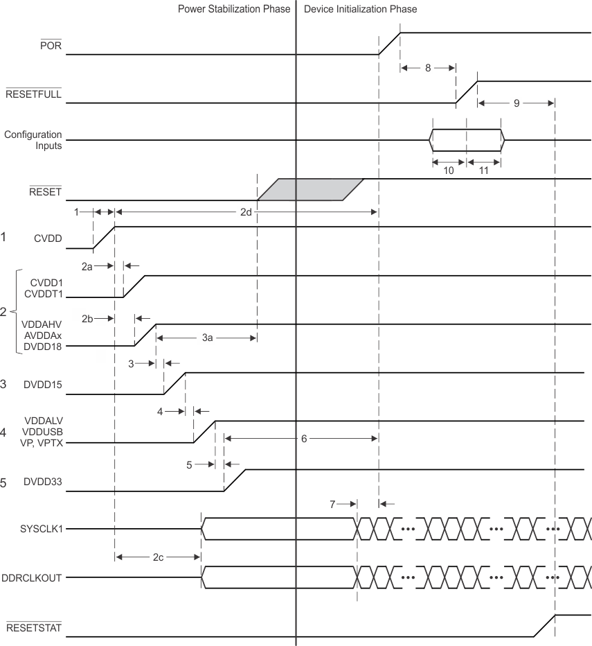
The details of the Core-before-IO power sequencing are defined in Table 11-2. Figure 11-1 shows power sequencing and reset control of the 66AK2Hxx. POR may be removed after the power has been stable for the required 100 µsec. RESETFULL must be held low for a period (see item 9 in Figure 11-1) after the rising edge of POR, but may be held low for longer periods if necessary. The configuration bits shared with the GPIO pins will be latched on the rising edge of RESETFULL and must meet the setup and hold times specified. SYSCLK1 must always be active before POR can be removed.

NOTE

TI recommends a maximum of 80 ms between one power rail being valid and the next power rail in the sequence starting to ramp.

Table 11-2 Core-Before-IO Power Sequencing

ITEM SYSTEM STATE
1 Begin Power Stabilization Phase
  • CVDD (core AVS) ramps up.
  • POR must be held low through the power stabilization phase. Because POR is low, all the core logic that has asynchronous reset (created from POR) is put into the reset state.
  • Each supply must ramp monotonically and must reach a stable valid level in 20 ms or less.
2a
  • CVDD1 and CVDDT1 (core constant) ramps at the same time or within 80 ms of CVDD. Although ramping CVDD1 simultaneously with CVDD is permitted, the voltage for CVDD1 must never exceed CVDD until after CVDD has reached a valid voltage.
  • The purpose of ramping up the core supplies close to each other is to reduce crowbar current. CVDD1 should trail CVDD as this will ensure that the Word Lines (WLs) in the memories are turned off and there is no current through the memory bit cells. If, however, CVDD1 (core constant) ramps up before CVDD (core AVS), then the worst-case current could be on the order of twice the specified draw of CVDD1.
  • Each supply must ramp monotonically and must reach a stable valid level in 20 ms or less.
  • The timing for CVDD1 is based on CVDD valid. CVDD1 and DVDD18/ADDAVH/AVDDAx may be enabled at the same time but do not need to ramp simultaneously. CVDD1 may be valid before or after DVDD18/ADDAVH/AVDDAx are valid, as long as the timing above is met.
2b
  • VDDAHV, AVDDAx and DVDD18 ramp at the same time or shortly following CVDD. DVDD18 must be enabled within 80 ms of CVDD valid and must ramp monotonically and reach a stable level in 20ms or less. This results in no more than 100 ms from the time when CVDD is valid to the time when DVDD18 is valid.
  • Each supply must ramp monotonically and must reach a stable valid level in 20 ms or less.
  • The timing for DVDD18/ADDAVH/AVDDAx is based on CVDD valid. DVDD18/ADDAVH/AVDDAx and CVDD1and CVDDT1 may be enabled at the same time but do not need to ramp simultaneously. DVDD18/ADDAVH/AVDDAx may be valid before or after CVDD1 and CVDDT1 are valid, as long as the timing above is met.
2c
  • Once CVDD is valid, the clock drivers can be enabled. Although the clock inputs are not necessary at this time, they should either be driven with a valid clock or be held in a static state with one leg high and one leg low.
2d
  • The DDR3ACLK, DDR3BCLK and SYSCLK1 may begin to toggle anytime between when CVDD is at a valid level and the setup time before POR goes high specified by item 7.
3
  • DVDD15 can ramp up within 80ms of when DVDD18 is valid.
  • RESETSTAT is driven low once the DVDD18 supply is available.
  • All LVCMOS input and bidirectional pins must not be driven or pulled high until DVDD18 is present. Driving an input or bidirectional pin before DVDD18 is valid could cause damage to the device.
  • Each supply must ramp monotonically and must reach a stable valid level in 20 ms or less.
3a
  • RESET may be driven high any time after DVDD18 is at a valid level. RESET must be high before POR is driven high.
4
  • VDDALV, VDDUSB, VP and VPTX ramp up within 80ms of when DVDD15 is valid.
  • Each supply must ramp monotonically and must reach a stable valid level in 20 ms or less.
5
  • DVDD33 supply is ramped up within 80 ms of when VDDALV, VDDUSB, VP and VPTX are valid.
  • Each supply must ramp monotonically and must reach a stable valid level in 20 ms or less.
6
  • POR must continue to remain low for at least 100 μs after all power rails have stabilized.
End power stabilization phase
7
  • Device initialization requires 500 SYSCLK1 periods after the Power Stabilization Phase. The maximum clock period is 33.33 nsec, so a delay of an additional 16 μs is required before a rising edge of POR. The clock must be active during the entire 16 μs.
8
  • RESETFULL must be held low for at least 24 transitions of the SYSCLK1 after POR has stabilized at a high level.
9
  • The rising edge of the RESETFULL will remove the reset to the eFuse farm allowing the scan to begin.
  • Once device initialization and the eFuse farm scan are complete, the RESETSTAT signal is driven high. This delay will be 10000 to 50000 clock cycles.
End device initialization phase
10
  • GPIO configuration bits must be valid for at least 12 transitions of the SYSCLK1 before the rising edge of RESETFULL.
11
  • GPIO configuration bits must be held valid for at least 12 transitions of the SYSCLK1 after the rising edge of RESETFULL.
66AK2H14 66AK2H12 66AK2H06 Core_Before_IO_Power_Seq_with_ARM.gifFigure 11-1 Core-Before-IO Power Sequencing