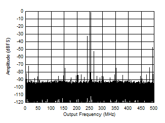
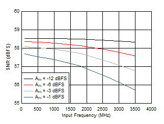
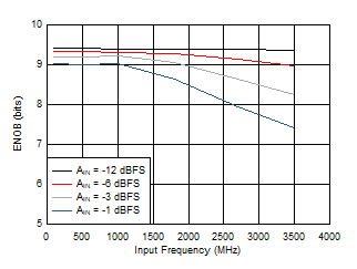
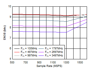
Typical values at 25°C, AIN
= -1 dBFS, FIN = 347 MHz, FS = 1600 MSPS, High power mode, FG
calibration, JMODE 0, C-PLL off, C-PLLREF = 50 MHz and VA11Q and VCLK11
noise suppression on when C-PLL on, Quad Channel operation, nominal supply voltages,
unless otherwise noted. SNR results exclude DC and HD2 to HD9; SINAD, ENOB, and SFDR
results exclude DC.
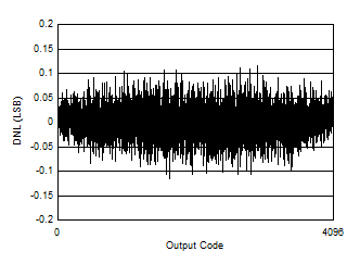
Figure 5-1 DNL
vs Code
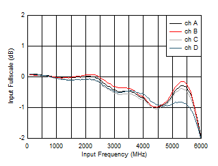
Figure 5-3 Input
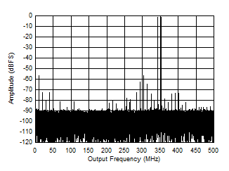
Fullscale vs Frequency![ADC12QJ1600-EP Single Tone FFT at 347 MHz and -1 dBFS ADC12QJ1600-EP Single Tone FFT at 347 MHz and -1 dBFS](/ods/images/ZHCSPX2B/GUID-DCD91D91-F346-4535-B5FC-4DF9B244FC7D-low.gif)
High
power mode, C-PLL on |
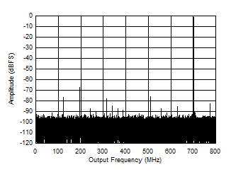
Figure 5-5 Single Tone FFT at 347 MHz and -1 dBFS
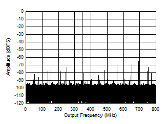
Figure 5-7 Single Tone FFT at 847 MHz and -1 dBFS![ADC12QJ1600-EP Single Tone FFT at 997 MHz and -1 dBFS ADC12QJ1600-EP Single Tone FFT at 997 MHz and -1 dBFS](/ods/images/ZHCSPX2B/GUID-C6C7CC36-1E06-47C5-8DD0-E312EE6CB7BB-low.gif)
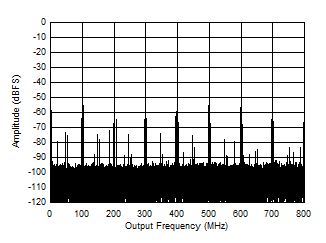
High
power mode, C-PLL on, Noise suppression off |
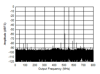
Figure 5-9 Single Tone FFT at 997 MHz and -1 dBFS
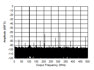
Figure 5-11 Single Tone FFT at 3797 MHz and -1 dBFS![ADC12QJ1600-EP Single Tone FFT at 347 MHz and -1 dBFS ADC12QJ1600-EP Single Tone FFT at 347 MHz and -1 dBFS](/ods/images/ZHCSPX2B/GUID-30FE71C8-7B20-483C-93DF-7ED2CD0D0EF4-low.gif)
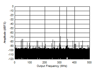
C-PLL on, Low power mode, FS = 1000
MSPS |
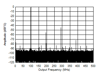
Figure 5-13 Single Tone FFT at 347 MHz and -1 dBFS![ADC12QJ1600-EP Single Tone FFT at 2097 MHz and -1 dBFS ADC12QJ1600-EP Single Tone FFT at 2097 MHz and -1 dBFS](/ods/images/ZHCSPX2B/GUID-6273920C-8CBC-47F9-8D58-77B5A1C7C419-low.gif)
Low
power mode, FS = 1000 MSPS |
Figure 5-15 Single Tone FFT at 2097 MHz and -1 dBFS
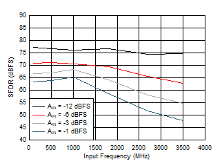
Figure 5-17 SFDR
vs Input Frequency
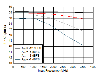
Figure 5-19 SINAD
vs Input Frequency
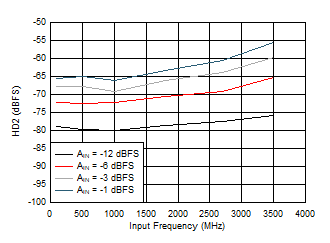
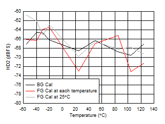
Figure 5-21 HD2
vs Input Frequency
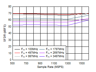
Figure 5-23 SFDR
vs Sample Rate
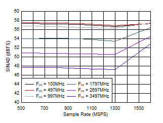
Figure 5-25 SINAD
vs Sample Rate
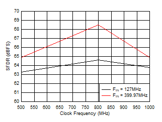
Figure 5-27 SFDR
vs Sample Rate
Figure 5-29 SFDR
vs Sample Rate
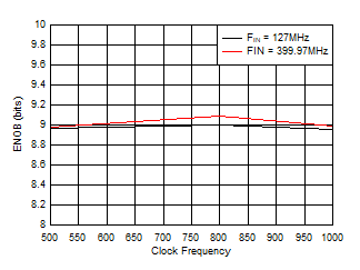
Figure 5-31 ENOB
vs Sample Rate
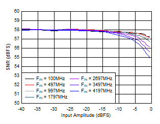
Figure 5-33 SNR
vs AIN![ADC12QJ1600-EP SNR
vs AIN ADC12QJ1600-EP SNR
vs AIN](/ods/images/ZHCSPX2B/GUID-417F5638-345C-44C0-B79F-01083CA58A6B-low.gif)
FIN = 100MHz, Low power mode |
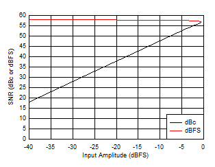
Figure 5-35 SNR
vs AIN
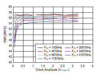
Figure 5-37 SNR
vs ACLK
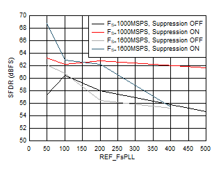
Figure 5-39 SFDR
vs FREF and Suppression
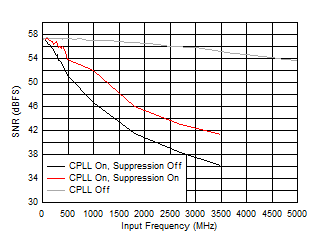
Figure 5-41 SNR
vs FIN and C-PLL modes
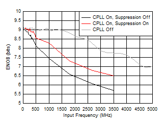
Figure 5-43 ENOB
vs FIN and C-PLL modes
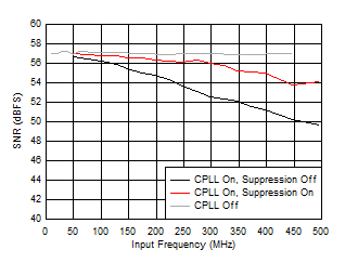
Figure 5-45 SNR
vs FIN and C-PLL modes
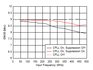
Figure 5-47 ENOB
vs FIN and C-PLL modes
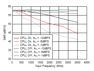
Figure 5-49 SNR
vs AIN and C-PLL
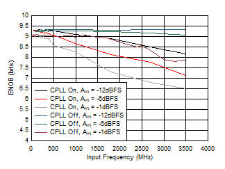
Figure 5-51 ENOB
vs AIN and C-PLL
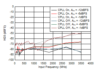
Figure 5-53 HD3
vs AIN and C-PLL
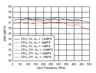
Figure 5-55 SNR
vs AIN and C-PLL
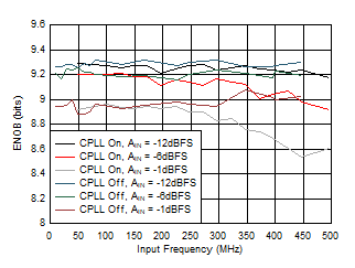
Figure 5-57 ENOB
vs AIN and C-PLL
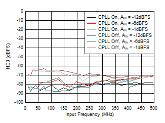
Figure 5-59 HD3
vs AIN and C-PLL![ADC12QJ1600-EP HD2,
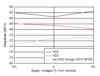
HD3 and Worst non-HD Spur vs Supply Voltage ADC12QJ1600-EP HD2,
HD3 and Worst non-HD Spur vs Supply Voltage](/ods/images/ZHCSPX2B/GUID-89B6B34A-3542-4445-937A-3E692DEED6EE-low.gif)
All
supplies changed together, high power mode |
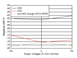
Figure 5-61 HD2,
HD3 and Worst non-HD Spur vs Supply Voltage![ADC12QJ1600-EP HD2,
HD3 and Worst non-HD Spur vs Supply Voltage ADC12QJ1600-EP HD2,
HD3 and Worst non-HD Spur vs Supply Voltage](/ods/images/ZHCSPX2B/GUID-36087026-C634-43E9-90B1-1D8BAB61DDEA-low.gif)
All
supplies changed together, low power mode, FS
= 1000MSPS |
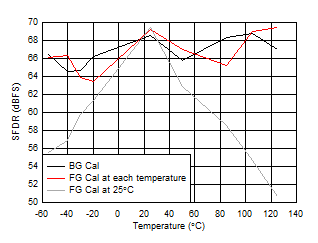
Figure 5-63 HD2,
HD3 and Worst non-HD Spur vs Supply Voltage
Figure 5-65 SFDR
vs Temperature
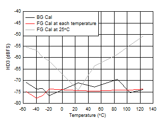
Figure 5-67 HD3
vs Temperature
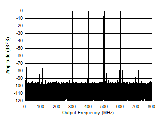
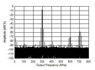
Figure 5-69 Two
Tone FFT at 498MHz
Figure 5-71 Two
Tone FFT at 3498MHz![ADC12QJ1600-EP Two
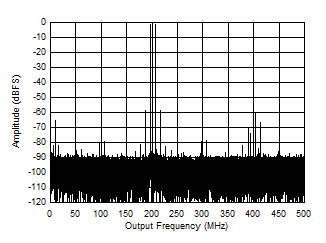
Tone FFT at 1798 MHz ADC12QJ1600-EP Two
Tone FFT at 1798 MHz](/ods/images/ZHCSPX2B/GUID-85991131-CDC5-4DFC-9285-9BCBC6DED247-low.gif)
10
MHz tone spacing, -7 dBFS per tone, Low power mode,
1000MSPS |
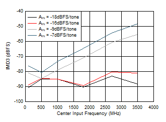
Figure 5-73 Two
Tone FFT at 1798 MHz
Figure 5-75 IMD3
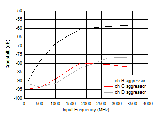
vs FIN
Figure 5-77 Crosstalk to Channel A vs FIN![ADC12QJ1600-EP Quad
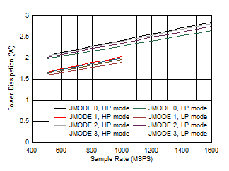
Channel, Power Dissipation vs FS and JMODES 0 - 3 ADC12QJ1600-EP Quad
Channel, Power Dissipation vs FS and JMODES 0 - 3](/ods/images/ZHCSPX2B/GUID-5A8EEBA8-06AF-4288-9BA9-1BD275283263-low.gif)
Low
power background calibration mode |
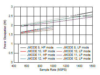
Figure 5-79 Quad
Channel, Power Dissipation vs FS and JMODES 0 - 3![ADC12QJ1600-EP Quad
Channel, Power Dissipation vs FS and JMODE 8 - 12 ADC12QJ1600-EP Quad
Channel, Power Dissipation vs FS and JMODE 8 - 12](/ods/images/ZHCSPX2B/GUID-2818A5D3-6DB0-4AE3-87F4-C3CE153EF760-low.gif)
Low
power background calibration mode |
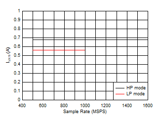
Figure 5-81 Quad
Channel, Power Dissipation vs FS and JMODE 8 - 12![ADC12QJ1600-EP Quad
Channel, IVA19 vs FS ADC12QJ1600-EP Quad
Channel, IVA19 vs FS](/ods/images/ZHCSPX2B/GUID-F9739491-36E0-4344-B0EF-F013038B5BD6-low.gif)
Low
power background calibration mode, independent of
JMODE |
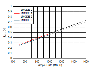
Figure 5-83 Quad
Channel, IVA19 vs FS![ADC12QJ1600-EP Quad
Channel, IVD11 vs FS and JMODE 0 - 3 ADC12QJ1600-EP Quad
Channel, IVD11 vs FS and JMODE 0 - 3](/ods/images/ZHCSPX2B/GUID-3372FD3F-6631-4029-8A61-F8263370B995-low.gif)
Low
power background calibration mode, independent of power
mode |
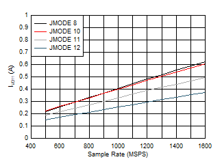
Figure 5-85 Quad
Channel, IVD11 vs FS and JMODE 0 - 3![ADC12QJ1600-EP Quad
Channel, IVD11 vs FS and JMODE 8 - 12 ADC12QJ1600-EP Quad
Channel, IVD11 vs FS and JMODE 8 - 12](/ods/images/ZHCSPX2B/GUID-9258FA56-B9C9-44A4-9CA2-A82F77920543-low.gif)
Low
power background calibration mode, independent of power
mode |
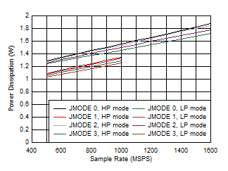
Figure 5-87 Quad
Channel, IVD11 vs FS and JMODE 8 - 12![ADC12QJ1600-EP Dual
Channel, Power Dissipation vs FS and JMODE 0 - 3 ADC12QJ1600-EP Dual
Channel, Power Dissipation vs FS and JMODE 0 - 3](/ods/images/ZHCSPX2B/GUID-8006A744-E08F-41BF-BBFA-DE5F512A17FD-low.gif)
Low
power background calibration mode |
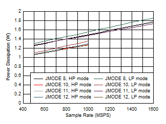
Figure 5-89 Dual
Channel, Power Dissipation vs FS and JMODE 0 - 3![ADC12QJ1600-EP Dual
Channel, Power Dissipation vs FS and JMODE 8 - 12 ADC12QJ1600-EP Dual
Channel, Power Dissipation vs FS and JMODE 8 - 12](/ods/images/ZHCSPX2B/GUID-6ECA4F20-E6DC-4BF4-AD23-730E05F1196B-low.gif)
Low
power background calibration mode |
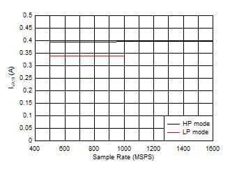
Figure 5-91 Dual
Channel, Power Dissipation vs FS and JMODE 8 - 12![ADC12QJ1600-EP Dual
Channel, IVA19 vs FS ADC12QJ1600-EP Dual
Channel, IVA19 vs FS](/ods/images/ZHCSPX2B/GUID-2D379B5C-B17F-418E-83E3-00B6A4FF9075-low.gif)
Low
power background calibration mode, independent of
JMODE |
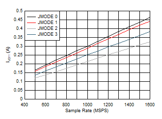
Figure 5-93 Dual
Channel, IVA19 vs FS![ADC12QJ1600-EP Dual
Channel, Power Dissipation vs FS and JMODE 0 - 3 ADC12QJ1600-EP Dual
Channel, Power Dissipation vs FS and JMODE 0 - 3](/ods/images/ZHCSPX2B/GUID-B92C5A88-54A3-45C4-9748-0CE0A7F1C50F-low.gif)
Low
power background calibration mode, independent of power
mode |
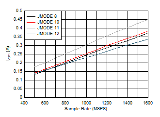
Figure 5-95 Dual
Channel, Power Dissipation vs FS and JMODE 0 - 3![ADC12QJ1600-EP Dual
Channel, Power Dissipation vs FS and JMODE 8 - 12 ADC12QJ1600-EP Dual
Channel, Power Dissipation vs FS and JMODE 8 - 12](/ods/images/ZHCSPX2B/GUID-5D7DC89B-54E0-4F08-87F3-C5E44D447C97-low.gif)
Low
power background calibration mode, independent of power
mode |
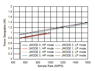
Figure 5-97 Dual
Channel, Power Dissipation vs FS and JMODE 8 - 12![ADC12QJ1600-EP Single Channel, Power Dissipation vs FS and JMODE 0 - 3 ADC12QJ1600-EP Single Channel, Power Dissipation vs FS and JMODE 0 - 3](/ods/images/ZHCSPX2B/GUID-A6FD7962-81A9-4C52-912E-E3D959A06401-low.gif)
Low
power background calibration mode |
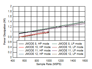
Figure 5-99 Single Channel, Power Dissipation vs FS and JMODE 0 - 3![ADC12QJ1600-EP Single Channel, Power Dissipation vs FS and JMODE 8 - 12 ADC12QJ1600-EP Single Channel, Power Dissipation vs FS and JMODE 8 - 12](/ods/images/ZHCSPX2B/GUID-96638E12-DDF8-4178-AC02-42EF3AC1E23C-low.gif)
Low
power background calibration mode |
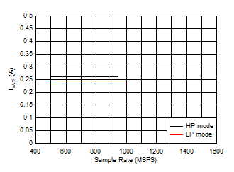
Figure 5-101 Single Channel, Power Dissipation vs FS and JMODE 8 - 12![ADC12QJ1600-EP Single Channel, IVA19 vs FS ADC12QJ1600-EP Single Channel, IVA19 vs FS](/ods/images/ZHCSPX2B/GUID-6AE3A149-ADB4-4359-B97F-6474BC4AF25B-low.gif)
Low
power background calibration mode, independent of
JMODE |
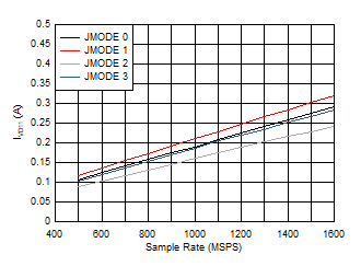
Figure 5-103 Single Channel, IVA19 vs FS![ADC12QJ1600-EP Single Channel, IVD11 vs FS and JMODE 0 - 3 ADC12QJ1600-EP Single Channel, IVD11 vs FS and JMODE 0 - 3](/ods/images/ZHCSPX2B/GUID-C94DCC18-7C60-4916-B957-24A4B70753EB-low.gif)
Low
power background calibration mode |
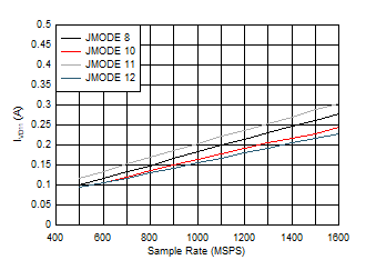
Figure 5-105 Single Channel, IVD11 vs FS and JMODE 0 - 3![ADC12QJ1600-EP Single Channel, IVD11 vs FS and JMODE 8 - 12 ADC12QJ1600-EP Single Channel, IVD11 vs FS and JMODE 8 - 12](/ods/images/ZHCSPX2B/GUID-DB33003F-DA24-4204-8406-D3ABA6750592-low.gif)
Low
power background calibration mode |
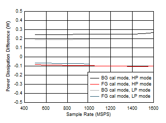
Figure 5-107 Single Channel, IVD11 vs FS and JMODE 8 - 12![ADC12QJ1600-EP Quad
Channel, Power Dissipation Change with Calibration Mode ADC12QJ1600-EP Quad
Channel, Power Dissipation Change with Calibration Mode](/ods/images/ZHCSPX2B/GUID-65777A4C-474B-421D-9BDC-C8464C1C6F29-low.gif)
Difference to lower power background calibration, JMODE
independent |
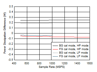
Figure 5-109 Quad
Channel, Power Dissipation Change with Calibration Mode![ADC12QJ1600-EP Single Channel, Power Dissipation Change with Calibration Mode ADC12QJ1600-EP Single Channel, Power Dissipation Change with Calibration Mode](/ods/images/ZHCSPX2B/GUID-37FED238-6264-4B28-B8B8-04DA515658C0-low.gif)
Difference to lower power background calibration, JMODE
independent |
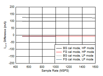
Figure 5-111 Single Channel, Power Dissipation Change with Calibration Mode![ADC12QJ1600-EP Dual
Channel, IVA19 Change with Calibration Mode ADC12QJ1600-EP Dual
Channel, IVA19 Change with Calibration Mode](/ods/images/ZHCSPX2B/GUID-CE669145-0C81-403D-BDE9-BED6239A8282-low.gif)
Difference to lower power background calibration, JMODE
independent |
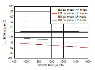
Figure 5-113 Dual
Channel, IVA19 Change with Calibration Mode![ADC12QJ1600-EP Quad
Channel, IVA11 Change with Calibration Mode ADC12QJ1600-EP Quad
Channel, IVA11 Change with Calibration Mode](/ods/images/ZHCSPX2B/GUID-6294BAAE-5743-4E60-BEA2-AF5FFDAEC4EA-low.gif)
Difference to lower power background calibration, JMODE
independent |
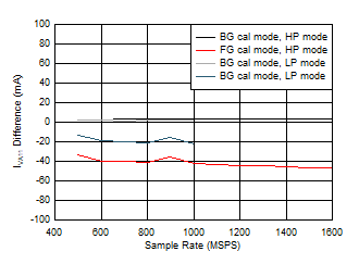
Figure 5-115 Quad
Channel, IVA11 Change with Calibration Mode![ADC12QJ1600-EP Single Channel, IVA11 Change with Calibration Mode ADC12QJ1600-EP Single Channel, IVA11 Change with Calibration Mode](/ods/images/ZHCSPX2B/GUID-C21D1D85-DBEC-4ABE-BB3D-0C3700D388A8-low.gif)
Difference to lower power background calibration, JMODE
independent |
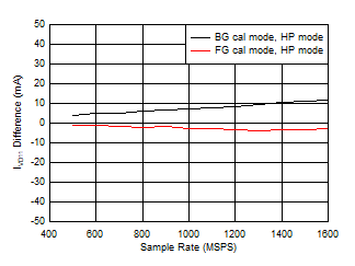
Figure 5-117 Single Channel, IVA11 Change with Calibration Mode![ADC12QJ1600-EP Dual
Channel, IVD11 Change with Calibration Mode ADC12QJ1600-EP Dual
Channel, IVD11 Change with Calibration Mode](/ods/images/ZHCSPX2B/GUID-AFDD79F3-2AAC-4E2F-B486-E5ED0B83F29B-low.gif)
Difference to lower power background calibration, JMODE
independent |
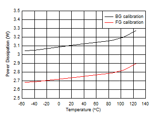
Figure 5-119 Dual
Channel, IVD11 Change with Calibration Mode
Figure 5-121 Quad
Channel, Power Dissipation vs Temperature
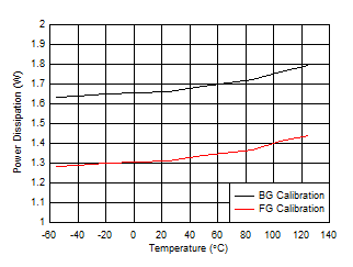
Figure 5-123 Single Channel, Power Dissipation vs Temperature![ADC12QJ1600-EP Background Calibration Core Transition (offset voltage) ADC12QJ1600-EP Background Calibration Core Transition (offset voltage)](/ods/images/ZHCSPX2B/GUID-6376349E-1F6D-4EFF-9F58-B844DF1DA934-low.gif)
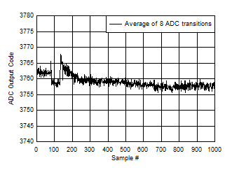
BG
Calibration, input voltage offset ~ 90% of fullscale,
ADC_SRC_DLY=31, MUX_DLY=30 |
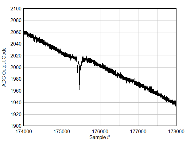
Figure 5-125 Background Calibration Core Transition (offset voltage)![ADC12QJ1600-EP Background Calibration Core Transition (AC Signal Zoomed) ADC12QJ1600-EP Background Calibration Core Transition (AC Signal Zoomed)](/ods/images/ZHCSPX2B/GUID-68DA1713-F3D4-4985-9D09-957F9A4B8654-low.gif)
BG
Calibration, ADC_SRC_DLY=31, MUX_DLY=30, unzoomed region
shown in previous plot |
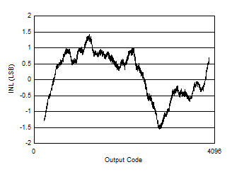
Figure 5-127 Background Calibration Core Transition (AC Signal Zoomed)
Figure 5-2 INL
vs Code
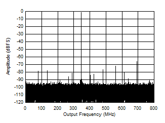
Figure 5-4 Single Tone FFT at 347 MHz and -1 dBFS![ADC12QJ1600-EP Single Tone FFT at 347 MHz and -1 dBFS ADC12QJ1600-EP Single Tone FFT at 347 MHz and -1 dBFS](/ods/images/ZHCSPX2B/GUID-CBA07BA5-E77B-4B84-8214-2EF48A2BFA71-low.gif)
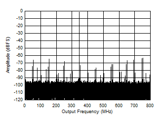
High
power mode, C-PLL on, Noise suppression off |
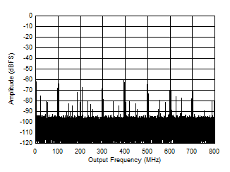
Figure 5-6 Single Tone FFT at 347 MHz and -1 dBFS![ADC12QJ1600-EP Single Tone FFT at 997 MHz and -1 dBFS ADC12QJ1600-EP Single Tone FFT at 997 MHz and -1 dBFS](/ods/images/ZHCSPX2B/GUID-E6E42D19-6464-4116-B5B3-87B8DCB9CAF8-low.gif)
High
power mode, C-PLL on |
Figure 5-8 Single Tone FFT at 997 MHz and -1 dBFS
Figure 5-10 Single Tone FFT at 1797 MHz and -1 dBFS![ADC12QJ1600-EP Single Tone FFT at 347 MHz and -1 dBFS ADC12QJ1600-EP Single Tone FFT at 347 MHz and -1 dBFS](/ods/images/ZHCSPX2B/GUID-CE61F2EA-6592-49E2-8E81-1E10E9AA5320-low.gif)
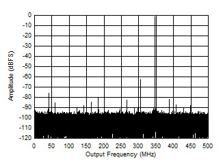
Low
power mode, FS = 1000 MSPS |
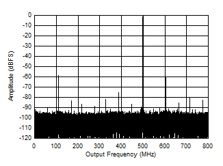
Figure 5-12 Single Tone FFT at 347 MHz and -1 dBFS![ADC12QJ1600-EP Single Tone FFT at 897 MHz and -1 dBFS ADC12QJ1600-EP Single Tone FFT at 897 MHz and -1 dBFS](/ods/images/ZHCSPX2B/GUID-0EF16BE6-AE72-4284-BD04-DDDA974DE5F5-low.gif)
Low
power mode, FS = 1000 MSPS |
Figure 5-14 Single Tone FFT at 897 MHz and -1 dBFS![ADC12QJ1600-EP Single Tone FFT at 3797 MHz and -1 dBFS ADC12QJ1600-EP Single Tone FFT at 3797 MHz and -1 dBFS](/ods/images/ZHCSPX2B/GUID-1E1D8EB2-76C3-4440-A0FC-54BC19B48DEB-low.gif)
Low
power mode, FS = 1000 MSPS |
Figure 5-16 Single Tone FFT at 3797 MHz and -1 dBFS
Figure 5-18 SNR
vs Input Frequency
Figure 5-20 ENOB
vs Input Frequency
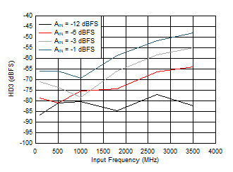
Figure 5-22 HD3
vs Input Frequency
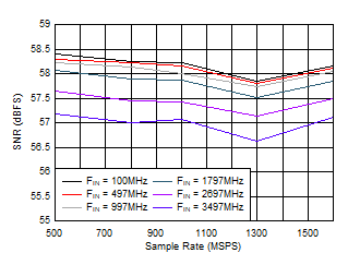
Figure 5-24 SNR
vs Sample Rate
Figure 5-26 ENOB
vs Sample Rate
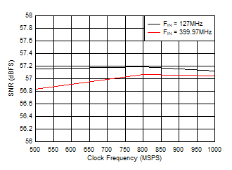
Figure 5-28 SNR
vs Sample Rate
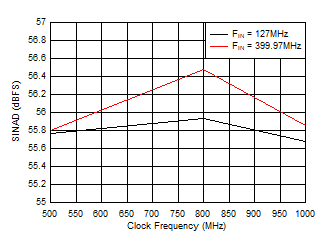
Figure 5-30 SINAD
vs Sample Rate
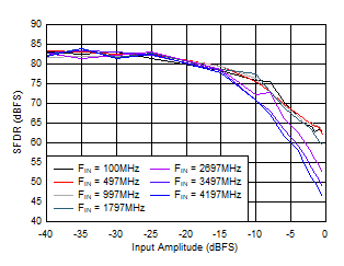
Figure 5-32 SFDR
vs AIN![ADC12QJ1600-EP SFDR
vs AIN ADC12QJ1600-EP SFDR
vs AIN](/ods/images/ZHCSPX2B/GUID-699FC4A5-21A3-4DA2-A441-0C850D49F865-low.gif)
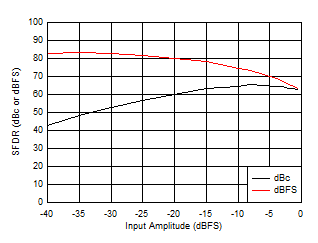
FIN = 100MHz, Low power mode |
Figure 5-34 SFDR
vs AIN
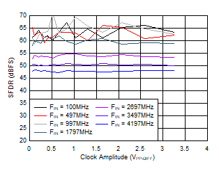
Figure 5-36 SFDR
vs ACLK
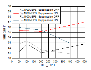
Figure 5-38 SNR
vs FREF and Suppression
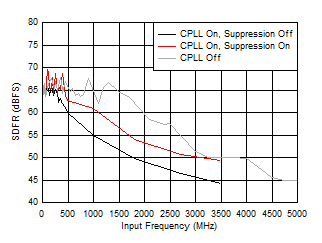
Figure 5-40 SFDR
vs FIN and C-PLL modes
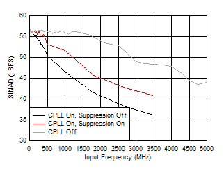
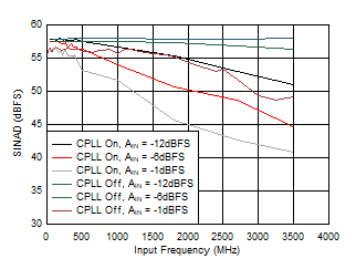
Figure 5-42 SINAD
vs FIN and C-PLL modes
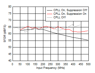
Figure 5-44 SFDR
vs FIN and C-PLL modes
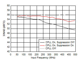
Figure 5-46 SINAD
vs FIN and C-PLL modes
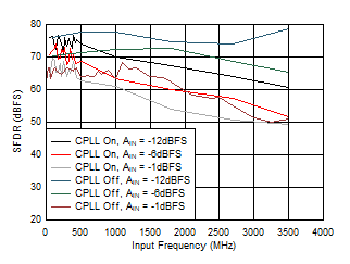
Figure 5-48 SFDR
vs AIN and C-PLL
Figure 5-50 SINAD
vs AIN and C-PLL
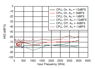
Figure 5-52 HD2
vs AIN and C-PLL
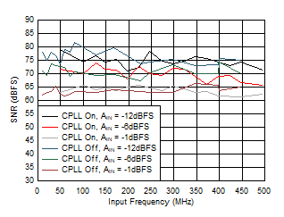
Figure 5-54 SFDR
vs AIN and C-PLL
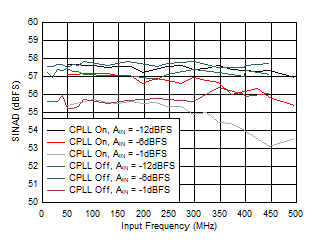
Figure 5-56 SINAD
vs AIN and C-PLL
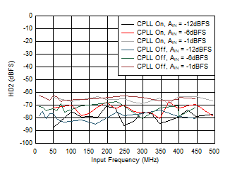
Figure 5-58 HD2
vs AIN and C-PLL![ADC12QJ1600-EP SNR,
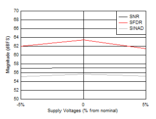
SFDR and SINAD vs Supply Voltage ADC12QJ1600-EP SNR,
SFDR and SINAD vs Supply Voltage](/ods/images/ZHCSPX2B/GUID-2E4C423A-7B90-4E00-A04C-AD3BCCB12BCC-low.gif)
All
supplies changed together, high power mode |
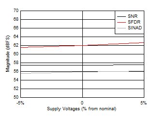
Figure 5-60 SNR,
SFDR and SINAD vs Supply Voltage![ADC12QJ1600-EP SNR,
SFDR and SINAD vs Supply Voltages ADC12QJ1600-EP SNR,
SFDR and SINAD vs Supply Voltages](/ods/images/ZHCSPX2B/GUID-20917AAC-9839-4F2C-A814-FB67555D6AE0-low.gif)
All
supplies changed together, low power mode, FS
= 1000MSPS |
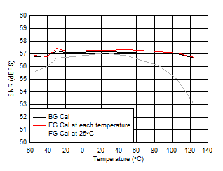
Figure 5-62 SNR,
SFDR and SINAD vs Supply Voltages
Figure 5-64 SNR
vs Temperature
Figure 5-66 HD2
vs Temperature![ADC12QJ1600-EP Worst
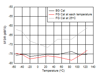
Spur vs Temperature ADC12QJ1600-EP Worst
Spur vs Temperature](/ods/images/ZHCSPX2B/GUID-19367162-AF81-4603-99E1-F00D0F8D94E8-low.gif)
Worst spur is non-HD2 though -HD10 SDFR |
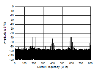
Figure 5-68 Worst
Spur vs Temperature
Figure 5-70 Two
Tone FFT at 1798MHz![ADC12QJ1600-EP Two
Tone FFT at 348 MHz ADC12QJ1600-EP Two
Tone FFT at 348 MHz](/ods/images/ZHCSPX2B/GUID-06FD51C1-27F1-44FE-A320-8BA75310984D-low.gif)
10
MHz tone spacing, -7 dBFS per tone, Low power mode,
1000MSPS |
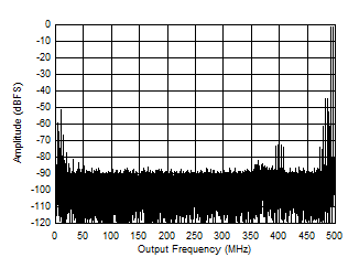
Figure 5-72 Two
Tone FFT at 348 MHz![ADC12QJ1600-EP Two
Tone FFT at 3498 MHz ADC12QJ1600-EP Two
Tone FFT at 3498 MHz](/ods/images/ZHCSPX2B/GUID-1F4F824C-E160-47A5-AE36-2CF4D5AC2628-low.gif)
10
MHz tone spacing, -7 dBFS per tone, Low power mode,
1000MSPS |
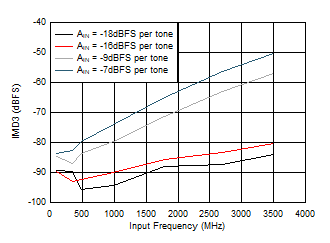
Figure 5-74 Two
Tone FFT at 3498 MHz![ADC12QJ1600-EP IMD3
vs FIN ADC12QJ1600-EP IMD3
vs FIN](/ods/images/ZHCSPX2B/GUID-D7E753EF-813B-46CE-82D5-5A218634B95A-low.gif)
10MHz tone spacing, Low power mode, 1000MSPS |
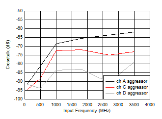
Figure 5-76 IMD3
vs FIN
Figure 5-78 Crosstalk to Channel B vs FIN![ADC12QJ1600-EP Quad
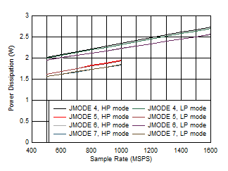
Channel, Power Dissipation vs FS and JMODE 4 - 7 ADC12QJ1600-EP Quad
Channel, Power Dissipation vs FS and JMODE 4 - 7](/ods/images/ZHCSPX2B/GUID-89330442-628F-4805-9F6E-67AFE1745973-low.gif)
Low
power background calibration mode |
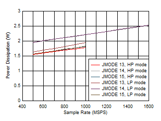
Figure 5-80 Quad
Channel, Power Dissipation vs FS and JMODE 4 - 7![ADC12QJ1600-EP Quad
Channel, Power Dissipation vs FS and JMODE 13 - 15 ADC12QJ1600-EP Quad
Channel, Power Dissipation vs FS and JMODE 13 - 15](/ods/images/ZHCSPX2B/GUID-F1F6D51F-989C-4E96-BFBB-CA432C70BC7B-low.gif)
Low
power background calibration mode |
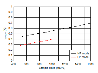
Figure 5-82 Quad
Channel, Power Dissipation vs FS and JMODE 13 - 15![ADC12QJ1600-EP Quad
Channel, IVA11 vs FS ADC12QJ1600-EP Quad
Channel, IVA11 vs FS](/ods/images/ZHCSPX2B/GUID-D0CA85CB-6A07-4854-8FD2-1A2E0DFD1E4C-low.gif)
Low
power background calibration mode, independent of
JMODE |
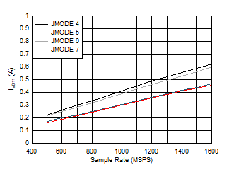
Figure 5-84 Quad
Channel, IVA11 vs FS![ADC12QJ1600-EP Quad
Channel, IVD11 vs FS and JMODE 4 - 7 ADC12QJ1600-EP Quad
Channel, IVD11 vs FS and JMODE 4 - 7](/ods/images/ZHCSPX2B/GUID-65BBFD99-5146-4B64-A44A-007411D927CA-low.gif)
Low
power background calibration mode, independent of power
mode |
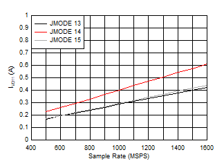
Figure 5-86 Quad
Channel, IVD11 vs FS and JMODE 4 - 7![ADC12QJ1600-EP Quad
Channel, IVD11 vs FS and JMODE 13 - 15 ADC12QJ1600-EP Quad
Channel, IVD11 vs FS and JMODE 13 - 15](/ods/images/ZHCSPX2B/GUID-9221A891-2DEF-4BA8-AE10-97FC2B04BDBE-low.gif)
Low
power background calibration mode, independent of power
mode |
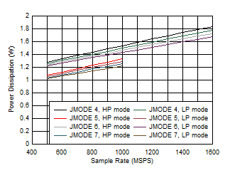
Figure 5-88 Quad
Channel, IVD11 vs FS and JMODE 13 - 15![ADC12QJ1600-EP Dual
Channel, Power Dissipation vs FS and JMODE 4 - 7 ADC12QJ1600-EP Dual
Channel, Power Dissipation vs FS and JMODE 4 - 7](/ods/images/ZHCSPX2B/GUID-CE4F48DF-BF92-4997-9EE6-58CD15E651AF-low.gif)
Low
power background calibration mode |
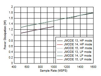
Figure 5-90 Dual
Channel, Power Dissipation vs FS and JMODE 4 - 7![ADC12QJ1600-EP Dual
Channel, Power Dissipation vs FS and JMODE 13 - 15 ADC12QJ1600-EP Dual
Channel, Power Dissipation vs FS and JMODE 13 - 15](/ods/images/ZHCSPX2B/GUID-786609D4-1911-4F63-B70B-D7D022B90D93-low.gif)
Low
power background calibration mode |
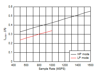
Figure 5-92 Dual
Channel, Power Dissipation vs FS and JMODE 13 - 15![ADC12QJ1600-EP Dual
Channel, IVA11 vs FS ADC12QJ1600-EP Dual
Channel, IVA11 vs FS](/ods/images/ZHCSPX2B/GUID-CDED0A0F-6FC1-43D6-A9AE-1BBA14E95944-low.gif)
Low
power background calibration mode, independent of
JMODE |
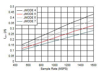
Figure 5-94 Dual
Channel, IVA11 vs FS![ADC12QJ1600-EP Dual
Channel, Power Dissipation vs FS and JMODE 4 - 7 ADC12QJ1600-EP Dual
Channel, Power Dissipation vs FS and JMODE 4 - 7](/ods/images/ZHCSPX2B/GUID-A306083E-9EEF-4F99-BFBE-4CD467D41196-low.gif)
Low
power background calibration mode, independent of power
mode |
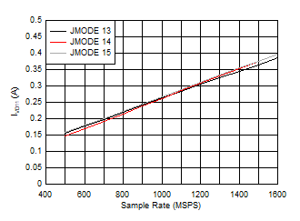
Figure 5-96 Dual
Channel, Power Dissipation vs FS and JMODE 4 - 7![ADC12QJ1600-EP Dual
Channel, Power Dissipation vs FS and JMODE 13 - 15 ADC12QJ1600-EP Dual
Channel, Power Dissipation vs FS and JMODE 13 - 15](/ods/images/ZHCSPX2B/GUID-7CE4D510-D833-4161-B237-358C4063EF5A-low.gif)
Low
power background calibration mode, independent of power
mode |
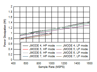
Figure 5-98 Dual
Channel, Power Dissipation vs FS and JMODE 13 - 15![ADC12QJ1600-EP Single Channel, Power Dissipation vs FS and JMODE 4 - 7 ADC12QJ1600-EP Single Channel, Power Dissipation vs FS and JMODE 4 - 7](/ods/images/ZHCSPX2B/GUID-2985F088-CAE5-4852-89F3-FAC6690ED8EF-low.gif)
Low
power background calibration mode |
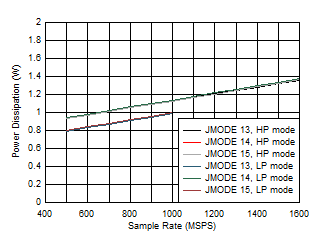
Figure 5-100 Single Channel, Power Dissipation vs FS and JMODE 4 - 7![ADC12QJ1600-EP Single Channel, Power Dissipation vs FS and JMODE 13 -
15 ADC12QJ1600-EP Single Channel, Power Dissipation vs FS and JMODE 13 -
15](/ods/images/ZHCSPX2B/GUID-2E843428-8788-4969-85C6-27EABCA7C9E5-low.gif)
Low
power background calibration mode |
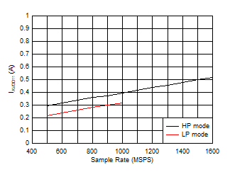
Figure 5-102 Single Channel, Power Dissipation vs FS and JMODE 13 -
15![ADC12QJ1600-EP Single Channel, IVA11 vs FS ADC12QJ1600-EP Single Channel, IVA11 vs FS](/ods/images/ZHCSPX2B/GUID-C6D072A5-EE44-4C93-BEA2-90A96A749F14-low.gif)
Low
power background calibration mode, independent of
JMODE |
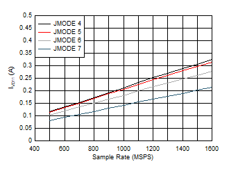
Figure 5-104 Single Channel, IVA11 vs FS![ADC12QJ1600-EP Single Channel, IVD11 vs FS and JMODE 4 - 7 ADC12QJ1600-EP Single Channel, IVD11 vs FS and JMODE 4 - 7](/ods/images/ZHCSPX2B/GUID-F771D4A3-4C03-432D-9542-BE87105A7702-low.gif)
Low
power background calibration mode |
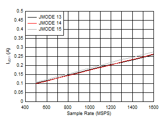
Figure 5-106 Single Channel, IVD11 vs FS and JMODE 4 - 7![ADC12QJ1600-EP Single Channel, IVD11 vs FS and JMODE 13 - 15 ADC12QJ1600-EP Single Channel, IVD11 vs FS and JMODE 13 - 15](/ods/images/ZHCSPX2B/GUID-409D5537-D241-4DA6-B2F8-19A34957E89C-low.gif)
Low
power background calibration mode |
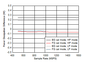
Figure 5-108 Single Channel, IVD11 vs FS and JMODE 13 - 15![ADC12QJ1600-EP Dual
Channel, Power Dissipation Change with Calibration Mode ADC12QJ1600-EP Dual
Channel, Power Dissipation Change with Calibration Mode](/ods/images/ZHCSPX2B/GUID-787A5138-9357-4144-B112-4F5A8E8FFB03-low.gif)
Difference to lower power background calibration, JMODE
independent |
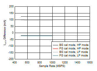
Figure 5-110 Dual
Channel, Power Dissipation Change with Calibration Mode![ADC12QJ1600-EP Quad
Channel, IVA19 Change with Calibration Mode ADC12QJ1600-EP Quad
Channel, IVA19 Change with Calibration Mode](/ods/images/ZHCSPX2B/GUID-5EBB7224-C8EC-40C5-B5FA-F3F328A13E8A-low.gif)
Difference to lower power background calibration, JMODE
independent |
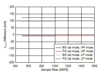
Figure 5-112 Quad
Channel, IVA19 Change with Calibration Mode![ADC12QJ1600-EP Single Channel, IVA19 Change with Calibration Mode ADC12QJ1600-EP Single Channel, IVA19 Change with Calibration Mode](/ods/images/ZHCSPX2B/GUID-C2F1217D-E334-4A8A-BDF3-32A7AD6DD564-low.gif)
Difference to lower power background calibration, JMODE
independent |
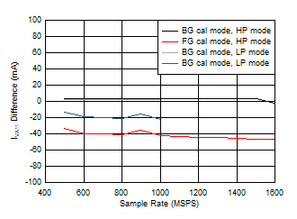
Figure 5-114 Single Channel, IVA19 Change with Calibration Mode![ADC12QJ1600-EP Dual
Channel, IVA11 Change with Calibration Mode ADC12QJ1600-EP Dual
Channel, IVA11 Change with Calibration Mode](/ods/images/ZHCSPX2B/GUID-F78BDE67-B128-4F79-A6E2-B5AFE6E2FDBC-low.gif)
Difference to lower power background calibration, JMODE
independent |
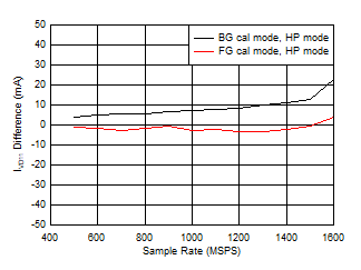
Figure 5-116 Dual
Channel, IVA11 Change with Calibration Mode![ADC12QJ1600-EP Quad
Channel, IVD11 Change with Calibration Mode ADC12QJ1600-EP Quad
Channel, IVD11 Change with Calibration Mode](/ods/images/ZHCSPX2B/GUID-C95B689A-E515-40E2-AF58-805D94ECA7EF-low.gif)
Difference to lower power background calibration, JMODE
independent |
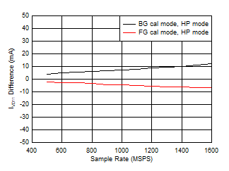
Figure 5-118 Quad
Channel, IVD11 Change with Calibration Mode![ADC12QJ1600-EP Single Channel, IVD11 Change with Calibration Mode ADC12QJ1600-EP Single Channel, IVD11 Change with Calibration Mode](/ods/images/ZHCSPX2B/GUID-B81D552A-E502-4239-AB84-71C2814C91C1-low.gif)
Difference to lower power background calibration, JMODE
independent |
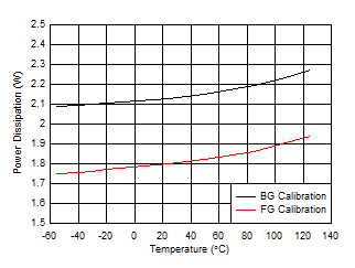
Figure 5-120 Single Channel, IVD11 Change with Calibration Mode
Figure 5-122 Dual
Channel, Power Dissipation vs Temperature![ADC12QJ1600-EP Background Calibration Core Transition (midscale voltage) ADC12QJ1600-EP Background Calibration Core Transition (midscale voltage)](/ods/images/ZHCSPX2B/GUID-F252D548-6E2B-4CF5-8FC1-D0D8F172DA5B-low.gif)
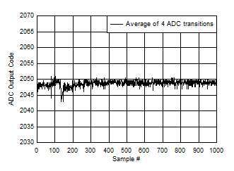
BG
Calibration, midscale input voltage, ADC_SRC_DLY=31,
MUX_DLY=30 |
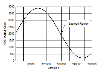
Figure 5-124 Background Calibration Core Transition (midscale voltage)![ADC12QJ1600-EP Background Calibration Core Transition (AC Signal) ADC12QJ1600-EP Background Calibration Core Transition (AC Signal)](/ods/images/ZHCSPX2B/GUID-AB89EEF4-4DEA-4518-BE14-A929A5E4B2DC-low.gif)
BG
Calibration, ADC_SRC_DLY=31, MUX_DLY=30, zoomed region
shown in next plot |
Figure 5-126 Background Calibration Core Transition (AC Signal)