ZHCSRD5 December 2022 ADC3544
PRODUCTION DATA
- 1 特性
- 2 应用
- 3 说明
- 4 Revision History
- 5 Pin Configuration and Functions
-
6 Specifications
- 6.1 Absolute Maximum Ratings
- 6.2 ESD Ratings
- 6.3 Recommended Operating Conditions
- 6.4 Thermal Information
- 6.5 Electrical Characteristics - Power Consumption
- 6.6 Electrical Characteristics - DC Specifications
- 6.7 Electrical Characteristics - AC Specifications
- 6.8 Timing Requirements
- 6.9 Typical Characteristics
- 7 Parameter Measurement Information
- 8 Detailed Description
- 9 Application Information Disclaimer
- 10Device and Documentation Support
- 11Mechanical, Packaging, and Orderable Information
8.3.4.1 Digital Filter Operation
The complex decimation operation is illustrated with an example in Figure 8-15. First the input signal (and the negative image) are frequency shifted by the NCO frequency as shown on the left. Next a digital filter is applied (centered around 0 Hz) and the output data rate is decimated - in this example the output data rate FS,OUT = FS/8 with a Nyquist zone of FS/16. During the complex mixing the spectrum (signal and noise) is split into real and complex parts and thus the amplitude is reduced by 6-dB. In order to compensate this loss, there is a 6-dB digital gain option in the decimation filter block that can be enabled via SPI write.
 Figure 8-15 Complex decimation
illustration
Figure 8-15 Complex decimation
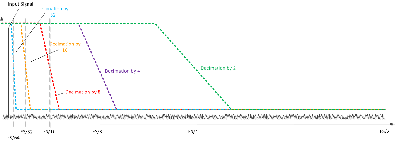
illustrationThe real decimation operation is illustrated with an example in Figure 8-16. There is no frequency shift happening and only the real portion of the complex digital filter is exercised. The output data rate is decimated - a decimation of 8 would result in an output data rate FS,OUT = FS/8 with a Nyquist zone of FS/16.
During the real mixing the spectrum (signal and noise) amplitude is reduced by 3-dB. In order to compensate this loss, there is a 3-dB digital gain option in the decimation filter block that can be enabled via SPI write.
 Figure 8-16 Real decimation
illustration