ZHCSKD9 October 2019 ADS1235-Q1
PRODUCTION DATA.
- 1 特性
- 2 应用
- 3 说明
- 4 修订历史记录
- 5 Pin Configuration and Functions
- 6 Specifications
- 7 Parameter Measurement Information
-
8 Detailed Description
- 8.1 Overview
- 8.2 Functional Block Diagram
- 8.3 Feature Description
- 8.4
Device Functional Modes
- 8.4.1 Conversion Control
- 8.4.2 Chop Mode
- 8.4.3 AC-Bridge Excitation Mode
- 8.4.4 ADC Clock Mode
- 8.4.5 Power-Down Mode
- 8.4.6 Reset
- 8.4.7 Calibration
- 8.5 Programming
- 8.6
Register Map
- 8.6.1 Device Identification (ID) Register (address = 00h) [reset = Cxh]
- 8.6.2 Device Status (STATUS) Register (address = 01h) [reset = 01h]
- 8.6.3 Mode 0 (MODE0) Register (address = 02h) [reset = 24h]
- 8.6.4 Mode 1 (MODE1) Register (address = 03h) [reset = 01h]
- 8.6.5 Mode 2 (MODE2) Register (address = 04h) [reset = 00h]
- 8.6.6 Mode 3 (MODE3) Register (address = 05h) [reset = 00h]
- 8.6.7 Reference Configuration (REF) Register (address = 06h) [reset = 05h]
- 8.6.8 Offset Calibration (OFCALx) Registers (address = 07h, 08h, 09h) [reset = 00h, 00h, 00h]
- 8.6.9 Full-Scale Calibration (FSCALx) Registers (address = 0Ah, 0Bh, 0Ch) [reset = 00h, 00h, 40h]
- 8.6.10 Reserved (RESERVED) Register (address = 0Dh) [reset = FFh]
- 8.6.11 Reserved (RESERVED) Register (address = 0Eh) [reset = 00h]
- 8.6.12 Reserved (RESERVED) Register (address = 0Fh) [reset = 00h]
- 8.6.13 PGA Configuration (PGA) Register (address = 10h) [reset = 00h]
- 8.6.14 Input Multiplexer (INPMUX) Register (address = 11h) [reset = FFh]
- 9 Application and Implementation
- 10Power Supply Recommendations
- 11Layout
- 12器件和文档支持
- 13机械、封装和可订购信息
8.3.2 PGA
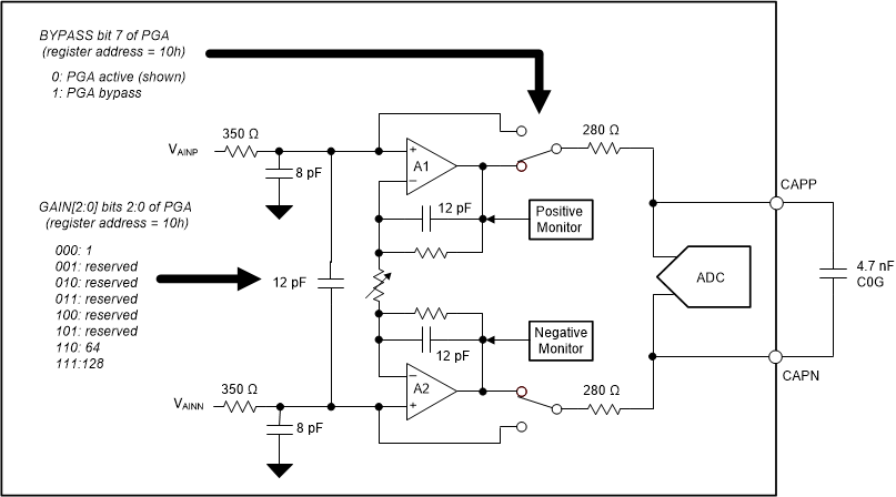
The PGA is a low-noise, CMOS differential-input, differential-output amplifier. The PGA extends the dynamic range of the ADC, important when used with low-level output sensors. Gain is controlled by the GAIN[2:0] register bits as shown in Figure 40. In PGA bypass mode, the input voltage range extends to the analog supplies. The PGA is powered down in bypass mode.
 Figure 40. PGA Block Diagram
 The PGA consists of two chopper-stabilized amplifiers (A1 and A2), and a resistor network that determines the PGA gain. The resistor network is precision-matched, providing low drift performance. The PGA has internal noise filters to reduce sensitivity to electromagnetic-interference (EMI). The PGA output is monitored to provide indication of a possible PGA overload condition.
Pins CAPP and CAPN are the PGA positive and negative outputs, respectively. Connect an external 4.7-nF capacitor (type C0G) as shown in Figure 40. The capacitor filters the sample pulses caused by the modulator, and with the internal resistors the antialias filter is provided. Place the capacitor as close as possible to the pins using short, direct traces. Avoid running clock traces or other digital traces close to these pins.