ZHCSIZ6C October 2018 – June 2019 ADS125H02
PRODUCTION DATA.
- 1 特性
- 2 应用
- 3 说明
- 4 修订历史记录
- 5 Device Comparison Table
- 6 Pin Configuration and Functions
- 7 Specifications
- 8 Parameter Measurement Information
-
9 Detailed Description
- 9.1 Overview
- 9.2 Functional Block Diagram
- 9.3 Feature Description
- 9.4 Device Functional Modes
- 9.5 Programming
- 9.6
Register Map
- 9.6.1 Device Identification (ID) Register (address = 00h) [reset = 6xh]
- 9.6.2 Main Status (STATUS0) Register (address = 01h) [reset = 01h]
- 9.6.3 Mode 0 (MODE0) Register (address = 02h) [reset = 24h]
- 9.6.4 Mode 1 (MODE1) Register (address = 03h) [reset = 01h]
- 9.6.5 Mode 2 (MODE2) Register (address = 04h) [reset = 00h]
- 9.6.6 Mode 3 (MODE3) Register (address = 05h) [reset = 00h]
- 9.6.7 Reference Configuration (REF) Register (address = 06h) [reset = 05h]
- 9.6.8 Offset Calibration (OFCALx) Registers (address = 07h, 08h, 09h) [reset = 00h, 00h, 00h]
- 9.6.9 Full-Scale Calibration (FSCALx) Registers (address = 0Ah, 0Bh, 0Ch) [reset = 00h, 00h, 40h]
- 9.6.10 Current Source Multiplexer (I_MUX) Register (address = 0Dh) [reset = FFh]
- 9.6.11 Current Source Magnitude (I_MAG) Register (address = 0Eh) [reset = 00h]
- 9.6.12 Reserved (RESERVED) Register (address = 0Fh) [reset = 00h]
- 9.6.13 MODE4 (MODE4) Register (address = 10h) [reset = 50h]
- 9.6.14 PGA Alarm (STATUS1) Register (address = 11h) [reset = xxh]
- 9.6.15 Status 2 (STATUS2) Register (address = 12h) [reset = 0xh]
- 10Application and Implementation
- 11Power Supply Recommendations
- 12Layout
- 13器件和文档支持
- 14机械、封装和可订购信息
9.3.3.2 PGA Monitor
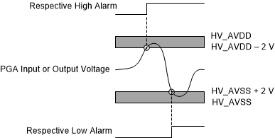
The PGA requires operating voltage headroom at the input and output nodes. The PGA must be within the linear operating range, otherwise the conversion data are not valid. Use the internal PGA monitors to assist in the detection of PGA overload. The PGA has four monitors (two monitors for the input and two monitors for the output) with high and low thresholds for each, for a total of eight possible alarms. The status of each PGA monitor is read in the STATUS1 register. The PGA monitoring points are illustrated in Figure 57. Figure 60 shows the operation of the low-overload threshold and the high-overload threshold of each PGA monitor point.
 Figure 60. PGA Monitor Thresholds
 Check for PGA overload by polling the STAT12 bit (bit 4 of the STATUS conversion byte or STATUS0 register). The STAT12 bit is the logical OR of all PGA error flags with the CRC-2 error flag. After the STAT12 bit asserts, poll the STATUS1 and STATUS2 registers (address 11h and 12h) to determine the source of the error. The status of the PGA overload is latched in the STATUS1 register and remains latched after the overload condition is removed. Reading the STATUS1 register clears the PGA overload bits (clear-on-read operation). The PGA overload flags and the CRC2 flag must be reset in order to clear the STAT12 bit. See the STATUS1 register for a description of the PGA overload bits.
The PGA monitors are analog comparators that can respond to transient overload conditions. Transient conditions can occur, for example, when multiplexing the inputs or when the gain is too high for the voltage of the next channel.