ZHCSF11B April   2016  – September 2016 ADS127L01

PRODUCTION DATA.  

  1. 特性
  2. 应用
  3. 说明
  4. 修订历史记录
  5. Pin Configuration and Functions
  6. Specifications
    1. 6.1  Absolute Maximum Ratings
    2. 6.2  ESD Ratings
    3. 6.3  Recommended Operating Conditions
    4. 6.4  Thermal Information
    5. 6.5  Electrical Characteristics
    6. 6.6  Timing Requirements: Serial Interface
    7. 6.7  Switching Characteristics: Serial Interface Mode
    8. 6.8  Timing Requirements: Frame-Sync Master Mode
    9. 6.9  Switching Characteristics: Frame-Sync Master Mode
    10. 6.10 Timing Requirements: Frame-Sync Slave Mode
    11. 6.11 Switching Characteristics: Frame-Sync Slave Mode
    12. 6.12 Typical Characteristics
  7. Parameter Measurement information
    1. 7.1 Noise Performance
  8. Detailed Description
    1. 8.1 Overview
    2. 8.2 Functional Block Diagram
    3. 8.3 Feature Description
      1. 8.3.1 Analog Inputs (AINP, AINN)
      2. 8.3.2 Digital Filter
        1. 8.3.2.1 Low-Latency Filter
          1. 8.3.2.1.1 Low-Latency Filter Frequency Response
          2. 8.3.2.1.2 Low-Latency Filter Settling Time
        2. 8.3.2.2 Wideband Filter
          1. 8.3.2.2.1 Wideband Filters Frequency Response
          2. 8.3.2.2.2 Wideband Filters Settling Time
      3. 8.3.3 Voltage Reference Inputs (REFP, REFN)
      4. 8.3.4 Clock Input (CLK)
      5. 8.3.5 Out-of-Range-Detect System Monitor
      6. 8.3.6 System Calibration
    4. 8.4 Device Functional Modes
      1. 8.4.1 Operating Modes (HR, LP, VLP)
      2. 8.4.2 Hardware Mode Pins
        1. 8.4.2.1 Interface Selection Pins (FORMAT, FSMODE)
        2. 8.4.2.2 Digital-Filter Path Selection Pins (FILTER[1:0])
        3. 8.4.2.3 Oversampling Ratio Selection Pins (OSR[1:0])
      3. 8.4.3 Start Pin (START)
      4. 8.4.4 Reset and Power-Down Pin (RESET/PWDN)
    5. 8.5 Programming
      1. 8.5.1 Serial Peripheral Interface (SPI) Programming
        1. 8.5.1.1 Chip Select (CS)
        2. 8.5.1.2 Serial Clock (SCLK)
        3. 8.5.1.3 Data Ready (DRDY/FSYNC)
        4. 8.5.1.4 Data Input (DIN)
        5. 8.5.1.5 Data Output (DOUT)
        6. 8.5.1.6 Daisy-Chain Input (DAISYIN)
        7. 8.5.1.7 SPI Timeout
        8. 8.5.1.8 SPI Commands
          1. 8.5.1.8.1 RESET (0000 011x)
          2. 8.5.1.8.2 START (0000 100x)
          3. 8.5.1.8.3 STOP (0000 101x)
          4. 8.5.1.8.4 RDATA (0001 0010)
          5. 8.5.1.8.5 RREG (0010 rrrr 0000 nnnn)
          6. 8.5.1.8.6 WREG (0100 rrrr 0000 nnnn)
      2. 8.5.2 Frame-Sync Programming
        1. 8.5.2.1 Frame-Sync Master Mode
          1. 8.5.2.1.1 Chip Select (CS) in Frame-Sync Master Mode
          2. 8.5.2.1.2 Serial Clock (SCLK) in Frame-Sync Master Mode
          3. 8.5.2.1.3 Frame-Sync (DRDY/FSYNC) in Frame-Sync Master Mode
          4. 8.5.2.1.4 Data Input (DIN) in Frame-Sync Master Mode
          5. 8.5.2.1.5 Data Output (DOUT) in Frame-Sync Master Mode
          6. 8.5.2.1.6 Daisy-Chain Input (DAISYIN) in Frame-Sync Master Mode
        2. 8.5.2.2 Frame-Sync Slave Mode
          1. 8.5.2.2.1 Chip Select (CS) in Frame-Sync Slave Mode
          2. 8.5.2.2.2 Serial Clock (SCLK) in Frame-Sync Slave Mode
          3. 8.5.2.2.3 Frame-Sync (DRDY/FSYNC) in Frame-Sync Slave Mode
          4. 8.5.2.2.4 Data Input (DIN) in Frame-Sync Slave Mode
          5. 8.5.2.2.5 Data Output (DOUT) in Frame-Sync Slave Mode
          6. 8.5.2.2.6 Daisy-Chain Input (DAISYIN) in Frame-Sync Slave Mode
      3. 8.5.3 Data Format
      4. 8.5.4 Status Word
      5. 8.5.5 Cyclic Redundancy Check (CRC)
        1. 8.5.5.1 Computing the CRC
    6. 8.6 Register Maps
      1. 8.6.1 ID: ID Control Register (address = 00h) [reset = x3h]
      2. 8.6.2 CONFIG: ADC Configuration Register (address = 01h) [reset = 00h]
      3. 8.6.3 OFC0: System Offset Calibration Register 0 (address = 02h) [reset = 00h]
      4. 8.6.4 OFC1: System Offset Calibration Register 1 (address = 03h) [reset = 00h]
      5. 8.6.5 OFC2: System Offset Calibration Register 2 (address = 04h) [reset = 00h]
      6. 8.6.6 FSC0: System Gain Calibration Register 0 (address = 05h) [reset = 00h]
      7. 8.6.7 FSC1: System Gain Calibration Register 1 (address = 06h) [reset = 80h]
      8. 8.6.8 MODE: Mode Settings (address = 07h) [reset = xxh]
  9. Application and Implementation
    1. 9.1 Application Information
      1. 9.1.1 Unused Inputs and Outputs
      2. 9.1.2 Multiple Device Configuration
        1. 9.1.2.1 Cascaded Configuration
          1. 9.1.2.1.1 SPI interface Mode
          2. 9.1.2.1.2 Frame-Sync interface Mode
        2. 9.1.2.2 Daisy-Chain Configuration
          1. 9.1.2.2.1 Daisy-Chain Operation Using SPI interface Mode
          2. 9.1.2.2.2 Daisy-Chain Operation Using Frame-Sync interface Mode
        3. 9.1.2.3 Synchronizing Devices
      3. 9.1.3 ADC Input Driver
        1. 9.1.3.1 Antialiasing Filter
        2. 9.1.3.2 Input Driver Selection
        3. 9.1.3.3 Amplifier Stability
      4. 9.1.4 Modulator Saturation
      5. 9.1.5 ADC Reference Driver
        1. 9.1.5.1 Single Chip Solution: REF6xxx
        2. 9.1.5.2 Multichip Solution: REF50xx + OPA320
      6. 9.1.6 Driving LVDD With an External Supply
    2. 9.2 Typical Application
      1. 9.2.1 Design Requirements
      2. 9.2.2 Detailed Design Procedure
      3. 9.2.3 Application Curves
    3. 9.3 Do's and Don'ts
    4. 9.4 Initialization Setup
  10. 10Power Supply Recommendations
    1. 10.1 Power-Supply Sequencing
    2. 10.2 Power-Supply Decoupling
  11. 11Layout
    1. 11.1 Layout Guidelines
    2. 11.2 Layout Example
  12. 12器件和文档支持
    1. 12.1 文档支持
      1. 12.1.1 相关文档 
    2. 12.2 接收文档更新通知
    3. 12.3 社区资源
    4. 12.4 商标
    5. 12.5 静电放电警告
    6. 12.6 Glossary
  13. 13机械、封装和可订购信息

封装选项

机械数据 (封装 | 引脚)
散热焊盘机械数据 (封装 | 引脚)
订购信息

特性

  • 数据速率:高达 512kSPS
  • 交流 + 直流性能:
    • 通带:最高可达 230kHz
    • 信噪比 (SNR):最高可达 115.5dB
    • 总谐波失真 (THD):低至 -129dB
    • 直流精度:
    • 偏移漂移:1.5μV/°C
    • 增益漂移:0.2ppm/°C
  • 运行模式:
    • 高分辨率(26mW 时为 128kSPS)
    • 低功耗(15mW 时为 128kSPS)
    • 超低功耗:105dB SNR(9mW 时为 128kSPS)
  • 数字滤波器选项:
    • 低延迟滤波器:正弦频率响应
    • 宽带 1 滤波器:
      (0.45 至 0.55) × fDATA 过渡带
    • 宽带 2 滤波器:
      (0.40 至 0.50) × fDATA 过渡带
  • SPI™或者帧同步串行接口
    • 兼容菊花链
  • 模拟电源:2.7V 到 3.6V
  • 数字电源:1.7V 到 3.6V
  • 工作温度范围:-40°C 至 +125°C

应用

  • 振动和模态分析
  • 数据采集系统
  • 声学和动态应力计
  • 电能质量分析

说明

ADS127L01 是一款 24 位 Δ-Σ 模数转换器 (ADC),其数据速率最高可达 512kSPS。该器件兼具出色直流精度和卓越交流性能。高阶、斩波稳定调制器在低带内噪声条件下实现极低漂移。集成抽取滤波器抑制调制器带外噪声。除低延迟滤波器外,ADS127L01 还提供多个纹波小于 ±0.00004dB 的宽带滤波器以及在奈奎斯特速率下实现 –116dB 阻带衰减的选项。

提供良好漂移性能的工业 Δ-Σ ADC 通常使用通带显著衰减的数字滤波器。因此,工业 Δ-Σ ADC 的信号带宽有限,主要用于直流测量。音频应用中的 高分辨率 ADC 提供 较大的可用带宽,但偏移和漂移规范明显弱于同类工业米6体育平台手机版_好二三四。ADS127L01 将这些转换器相结合,能够在 –40°C 到 +125°C 的工业温度范围内提供高精度工业测量,实现出色的直流和交流规范。

该器件的不同工作模式可优化速度、分辨率和功率。可编程串行接口具备 SPI、帧同步从器件或帧同步主器件这三个选项中的任意一个,可轻松跨越隔离栅与单片机或数字信号处理器 (DSP) 相连。

器件信息(1)

器件型号 封装 封装尺寸(标称值)
ADS127L01 TQFP (32) 5.00mm x 5.00mm
  1. 要了解所有可用封装,请参见数据表末尾的封装选项附录。

ADS127L01 框图
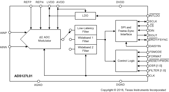
ADS127L01 Blockdiagram_sbas607.gif

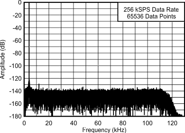
ADC 频谱

ADS127L01 fp_graph_sbas607.gif