ZHCS146C December 2011 – April 2020 ADS1291 , ADS1292 , ADS1292R
PRODUCTION DATA.
- 1 特性
- 2 应用
- 3 说明
- 4 修订历史记录
- 5 Pin Configuration and Functions
- 6 Specifications
- 7 Parameter Measurement Information
-
8 Detailed Description
- 8.1 Overview
- 8.2 Functional Block Diagram
- 8.3
Feature Description
- 8.3.1 EMI Filter
- 8.3.2
Input Multiplexer
- 8.3.2.1 Device Noise Measurements
- 8.3.2.2 Test Signals (TestP and TestN)
- 8.3.2.3 Auxiliary Differential Input (RESP_MODN/IN3N, RESP_MODN/IN3P)
- 8.3.2.4 Temperature Sensor (TEMPP, TEMPN)
- 8.3.2.5 Supply Measurements (MVDDP, MVDDN)
- 8.3.2.6 Lead-Off Excitation Signals (LoffP, LoffN)
- 8.3.2.7 Auxiliary Single-Ended Input
- 8.3.3 Analog Input
- 8.3.4 PGA Settings and Input Range
- 8.3.5 Digital Decimation Filter
- 8.3.6 Reference
- 8.3.7 Clock
- 8.3.8 Data Format
- 8.3.9 Multiple Device Configuration
- 8.3.10 ECG-Specific Functions
- 8.3.11 Setting the Device for Basic Data Capture
- 8.4 Device Functional Modes
- 8.5
Programming
- 8.5.1 SPI Interface
- 8.5.2
SPI Command Definitions
- 8.5.2.1 WAKEUP: Exit STANDBY Mode
- 8.5.2.2 STANDBY: Enter STANDBY Mode
- 8.5.2.3 RESET: Reset Registers to Default Values
- 8.5.2.4 START: Start Conversions
- 8.5.2.5 STOP: Stop Conversions
- 8.5.2.6 OFFSETCAL: Channel Offset Calibration
- 8.5.2.7 RDATAC: Read Data Continuous
- 8.5.2.8 SDATAC: Stop Read Data Continuous
- 8.5.2.9 RDATA: Read Data
- 8.5.2.10 Sending Multi-Byte Commands
- 8.5.2.11 RREG: Read From Register
- 8.5.2.12 WREG: Write to Register
- 8.6
Register Maps
- 8.6.1
User Register Description
- 8.6.1.1 ID: ID Control Register (Factory-Programmed, Read-Only) (address = 00h)
- 8.6.1.2 CONFIG1: Configuration Register 1 (address = 01h)
- 8.6.1.3 CONFIG2: Configuration Register 2 (address = 02h)
- 8.6.1.4 LOFF: Lead-Off Control Register (address = 03h)
- 8.6.1.5 CH1SET: Channel 1 Settings (address = 04h)
- 8.6.1.6 CH2SET: Channel 2 Settings (address = 05h)
- 8.6.1.7 RLD_SENS: Right Leg Drive Sense Selection (address = 06h)
- 8.6.1.8 LOFF_SENS: Lead-Off Sense Selection (address = 07h)
- 8.6.1.9 LOFF_STAT: Lead-Off Status (address = 08h)
- 8.6.1.10 RESP1: Respiration Control Register 1 (address = 09h)
- 8.6.1.11 RESP2: Respiration Control Register 2 (address = 0Ah)
- 8.6.1.12 GPIO: General-Purpose I/O Register (address = 0Bh)
- 8.6.1
User Register Description
- 9 Application and Implementation
- 10Power Supply Recommendations
- 11Layout
- 12器件和文档支持
- 13机械、封装和可订购信息
封装选项
机械数据 (封装 | 引脚)
散热焊盘机械数据 (封装 | 引脚)
订购信息
8.3.10.2.1 DC Lead-Off
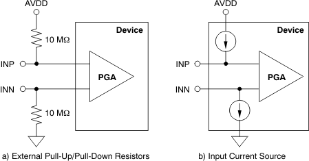
In this method, the lead-off excitation is with a dc signal. The dc excitation signal can be chosen from either an external pull-up or pull-down resistor or a current source or sink, as shown in Figure 38. One side of the channel is pulled to supply and the other side is pulled to ground. The internal current source and current sink can be swapped by setting the FLIP1 and FLIP2 bits in the LOFF_SENS register. In case of current source or sink, the magnitude of the current can be set by using the ILEAD_OFF[1:0] bits in the LOFF register. The current source or sink gives larger input impedance compared to the 10-MΩ pull-up or pull-down resistor.
 Figure 38. DC Lead-Off Excitation Options
 Sensing of the response can be done either by looking at the digital output code from the device or by monitoring the input voltages with an on-chip comparator. If either of the electrodes is off, the pull-up resistors and the pull-down resistors saturate the channel. By looking at the output code it can be determined that either the P-side or the N-side is off. To pinpoint which one is off, the comparators must be used. The input voltage is also monitored using a comparator and a 4-bit digital-to-analog converter (DAC) whose levels are set by the COMP_TH[2:0] bits in the LOFF register. The output of the comparators are stored in the LOFF_STAT register. These two registers are available as a part of the output data stream. (See the Data Output Protocol (DOUT) subsection of the SPI Interface section.) If dc lead-off is not used, the lead-off comparators can be powered down by setting the PD_LOFF_COMP bit in the CONFIG2 register.
An example procedure to turn on dc lead-off is given in the Lead-Off section.