ZHCSBL9F October   2012  – May 2016 ADS42LB49 , ADS42LB69

PRODUCTION DATA.  

  1. 特性
  2. 应用
  3. 说明
  4. 修订历史记录
  5. Pin Configuration and Functions
  6. Specifications
    1. 6.1  Absolute Maximum Ratings
    2. 6.2  ESD Ratings
    3. 6.3  Recommended Operating Conditions
    4. 6.4  Thermal Information
    5. 6.5  Electrical Characteristics: ADS42LB69 (16-Bit)
    6. 6.6  Electrical Characteristics: ADS42LB49 (14-Bit)
    7. 6.7  Electrical Characteristics: General
    8. 6.8  Digital Characteristics
    9. 6.9  Timing Requirements: General
    10. 6.10 Timing Requirements: DDR LVDS Mode
    11. 6.11 Timing Requirements: QDR LVDS Mode
    12. 6.12 Typical Characteristics: ADS42LB69
    13. 6.13 Typical Characteristics: ADS42LB49
    14. 6.14 Typical Characteristics: Common
    15. 6.15 Typical Characteristics: Contour
      1. 6.15.1 Spurious-Free Dynamic Range (SFDR): General
      2. 6.15.2 Signal-to-Noise Ratio (SNR): ADS42LB69
      3. 6.15.3 Signal-to-Noise Ratio (SNR): ADS42LB49
  7. Parameter Measurement Information
  8. Detailed Description
    1. 8.1 Overview
    2. 8.2 Functional Block Diagrams
    3. 8.3 Feature Description
      1. 8.3.1 Digital Gain
      2. 8.3.2 Input Clock Divider
      3. 8.3.3 Overrange Indication
        1. 8.3.3.1 OVR in a QDR Pinout
        2. 8.3.3.2 OVR in a DDR Pinout
        3. 8.3.3.3 Programming Threshold for Fast OVR
      4. 8.3.4 LVDS Buffer
      5. 8.3.5 Output Data Format
    4. 8.4 Device Functional Modes
      1. 8.4.1 Digital Output Information
        1. 8.4.1.1 Output Interface
        2. 8.4.1.2 DDR LVDS Outputs
        3. 8.4.1.3 QDR LVDS Outputs
    5. 8.5 Programming
      1. 8.5.1 Device Configuration
      2. 8.5.2 Details of Serial Interface
        1. 8.5.2.1 Register Initialization
        2. 8.5.2.2 Serial Register Write
        3. 8.5.2.3 Serial Register Readout
    6. 8.6 Register Maps
      1. 8.6.1 Description of Serial Interface Registers
        1. 8.6.1.1  Register 6 (offset = 06h) [reset = 80h]
        2. 8.6.1.2  Register 7 (offset = 07h) [reset = 00h]
        3. 8.6.1.3  Register 8 (offset = 08h) [reset = 00h]
        4. 8.6.1.4  Register B (offset = 0Bh) [reset = 00h]
        5. 8.6.1.5  Register C (offset = 0Ch) [reset = 00h]
        6. 8.6.1.6  Register D (offset = 0Dh) [reset = 6Ch]
        7. 8.6.1.7  Register F (offset = 0Fh) [reset = 00h]
        8. 8.6.1.8  Register 10 (offset = 10h) [reset = 00h]
        9. 8.6.1.9  Register 11 (offset = 11h) [reset = 00h]
        10. 8.6.1.10 Register 12 (offset = 12h) [reset = 00h]
        11. 8.6.1.11 Register 13 (offset = 13h) [reset = 00h]
        12. 8.6.1.12 Register 14 (offset = 14h) [reset = 00h]
        13. 8.6.1.13 Register 15 (offset = 15h) [reset = 00h]
        14. 8.6.1.14 Register 16 (offset = 16h) [reset = 00h]
        15. 8.6.1.15 Register 17 (offset = 17h) [reset = 00h]
        16. 8.6.1.16 Register 18 (offset = 18h) [reset = 00h]
        17. 8.6.1.17 Register 1F (offset = 1Fh) [reset = 7Fh]
        18. 8.6.1.18 Register 20 (offset = 20h) [reset = 00h]
  9. Application and Implementation
    1. 9.1 Application Information
    2. 9.2 Typical Application
      1. 9.2.1 Design Requirements
      2. 9.2.2 Detailed Design Procedure
        1. 9.2.2.1 Analog Input
          1. 9.2.2.1.1 Drive Circuit Requirements
          2. 9.2.2.1.2 Driving Circuit
          3. 9.2.2.1.3 Using the ADS42LBx9 In Time-Domain, Low-Frequency Pulse Applications
        2. 9.2.2.2 Clock Input
        3. 9.2.2.3 SNR and Clock Jitter
      3. 9.2.3 Application Curves
  10. 10Power Supply Recommendations
  11. 11Layout
    1. 11.1 Layout Guidelines
    2. 11.2 Layout Example
  12. 12器件和文档支持
    1. 12.1 相关链接
    2. 12.2 社区资源
    3. 12.3 商标
    4. 12.4 静电放电警告
    5. 12.5 Glossary
  13. 13机械、封装和可订购信息

封装选项

机械数据 (封装 | 引脚)
散热焊盘机械数据 (封装 | 引脚)
订购信息

7 Parameter Measurement Information

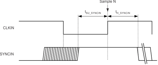
ADS42LB49 ADS42LB69 tim_syncin_las904.gif Figure 72. Timing Diagram for SYNCINP and SYNCINM Inputs
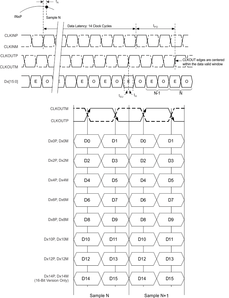
ADS42LB49 ADS42LB69 tim_DDR_LVDS_out_las904.gif Figure 73. DDR LVDS Output Timing Diagram
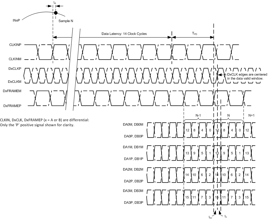
ADS42LB49 ADS42LB69 tim_DDR2X_LVDS_out_las904.gif Figure 74. QDR LVDS Output Timing Diagram
ADS42LB49 ADS42LB69 tim_lvds_vo_level_bas550.gif
1.

NOINDENT:

With an external 100-Ω termination.
Figure 75. DDR LVDS Output Voltage Levels