ZHCSEA4C May 2015 – December 2020 ADS54J40
PRODUCTION DATA
- 1 特性
- 2 应用
- 3 说明
- 4 Revision History
- 5 ADS54J40 Comparison
- 6 Pin Configuration and Functions
- 7 Specifications
-
8 Detailed Description
- 8.1 Overview
- 8.2 Functional Block Diagram
- 8.3 Feature Description
- 8.4 Device Functional Modes
- 8.5
Register Maps
- 8.5.1 Example Register Writes
- 8.5.2
Register Descriptions
- 8.5.2.1 General Registers
- 8.5.2.2
Master Page (080h) Registers
- 8.5.2.2.1 Register 20h (address = 20h), Master Page (080h)
- 8.5.2.2.2 Register 21h (address = 21h), Master Page (080h)
- 8.5.2.2.3 Register 23h (address = 23h), Master Page (080h)
- 8.5.2.2.4 Register 24h (address = 24h), Master Page (080h)
- 8.5.2.2.5 Register 26h (address = 26h), Master Page (080h)
- 8.5.2.2.6 Register 4Fh (address = 4Fh), Master Page (080h)
- 8.5.2.2.7 Register 53h (address = 53h), Master Page (080h)
- 8.5.2.2.8 Register 54h (address = 54h), Master Page (080h)
- 8.5.2.2.9 Register 55h (address = 55h), Master Page (080h)
- 8.5.2.2.10 Register 59h (address = 59h), Master Page (080h)
- 8.5.2.3 ADC Page (0Fh) Register
- 8.5.2.4
Main Digital Page (6800h) Registers
- 8.5.2.4.1 Register 0h (address = 0h), Main Digital Page (6800h)
- 8.5.2.4.2 Register 40h (address = 40h), Main Digital Page (6800h)
- 8.5.2.4.3 Register 41h (address = 41h), Main Digital Page (6800h)
- 8.5.2.4.4 Register 42h (address = 42h), Main Digital Page (6800h)
- 8.5.2.4.5 Register 43h (address = 43h), Main Digital Page (6800h)
- 8.5.2.4.6 Register 44h (address = 44h), Main Digital Page (6800h)
- 8.5.2.4.7 Register 4Bh (address = 4Bh), Main Digital Page (6800h)
- 8.5.2.4.8 Register 4Dh (address = 4Dh), Main Digital Page (6800h)
- 8.5.2.4.9 Register 4Eh (address = 4Eh), Main Digital Page (6800h)
- 8.5.2.4.10 Register 52h (address = 52h), Main Digital Page (6800h)
- 8.5.2.4.11 Register 68h (address = 68h), Main Digital Page (6800h)
- 8.5.2.4.12 Register 72h (address = 72h), Main Digital Page (6800h)
- 8.5.2.4.13 Register ABh (address = ABh), Main Digital Page (6800h)
- 8.5.2.4.14 Register ADh (address = ADh), Main Digital Page (6800h)
- 8.5.2.4.15 Register F7h (address = F7h), Main Digital Page (6800h)
- 8.5.2.5
JESD Digital Page (6900h) Registers
- 8.5.2.5.1 Register 0h (address = 0h), JESD Digital Page (6900h)
- 8.5.2.5.2 Register 1h (address = 1h), JESD Digital Page (6900h)
- 8.5.2.5.3 Register 2h (address = 2h), JESD Digital Page (6900h)
- 8.5.2.5.4 Register 3h (address = 3h), JESD Digital Page (6900h)
- 8.5.2.5.5 Register 5h (address = 5h), JESD Digital Page (6900h)
- 8.5.2.5.6 Register 6h (address = 6h), JESD Digital Page (6900h)
- 8.5.2.5.7 Register 7h (address = 7h), JESD Digital Page (6900h)
- 8.5.2.5.8 Register 16h (address = 16h), JESD Digital Page (6900h)
- 8.5.2.5.9 Register 31h (address = 31h), JESD Digital Page (6900h)
- 8.5.2.5.10 Register 32h (address = 32h), JESD Digital Page (6900h)
- 8.5.2.6
JESD Analog Page (6A00h) Registers
- 8.5.2.6.1 Register 12h (address = 12h), JESD Analog Page (6A00h)
- 8.5.2.6.2 Registers 13h-15h (addresses = 13h-5h), JESD Analog Page (6A00h)
- 8.5.2.6.3 Register 16h (address = 16h), JESD Analog Page (6A00h)
- 8.5.2.6.4 Register 17h (address = 17h), JESD Analog Page (6A00h)
- 8.5.2.6.5 Register 1Ah (address = 1Ah), JESD Analog Page (6A00h)
- 8.5.2.6.6 Register 1Bh (address = 1Bh), JESD Analog Page (6A00h)
- 8.5.2.7
Offset Read Page (JESD BANK PAGE SEL = 6100h, JESD BANK PAGE SEL1
= 0000h) Registers
- 8.5.2.7.1 Register 068h (address = 068h), Offset Read Page
- 8.5.2.7.2 Register 069h (address = 069h), Offset Read Page
- 8.5.2.7.3 Registers 074h, 076h, 078h, 7Ah (address = 074h, 076h, 078h, 7Ah), Offset Read Page
- 8.5.2.7.4 Registers 075h, 077h, 079h, 7Bh (address = 075h, 077h, 079h, 7Bh), Offset Read Page
- 8.5.2.8 Offset Load Page (JESD BANK PAGE SEL= 6100h, JESD BANK PAGE SEL1 = 0500h) Registers
- 9 Application Information Disclaimer
- 10Power Supply Recommendations
- 11Layout
- 12Device and Documentation Support
7.8 Timing Requirements
Typical values are at TA = 25°C, full temperature range is from TMIN = –40°C to TMAX = 85°C, ADC sampling rate = 1.0 GSPS, 50% clock duty cycle, AVDD3V = 3.0 V, AVDD = DVDD = 1.9 V, IOVDD = 1.15 V, and –1-dBFS differential input, unless otherwise noted.
| MIN | TYP | MAX | UNITS | |||
|---|---|---|---|---|---|---|
| SAMPLE TIMING (TBD are any of these Switching Characteristics?TBD: No) | ||||||
| Aperture delay | 0.75 | 1.6 | ns | |||
| Aperture delay matching between two channels on the same device | ±70 | ps | ||||
| Aperture delay matching between two devices at the same temperature and supply voltage | ±270 | ps | ||||
| Aperture jitter | 120 | fS rms | ||||
| WAKE-UP TIMING | ||||||
| Wake-up time to valid data after coming out of global power-down | 150 | µs | ||||
| LATENCY(1) | ||||||
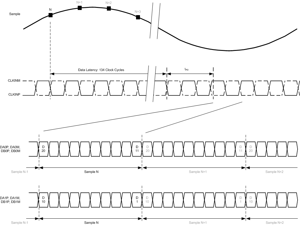
| Data latency: ADC sample to digital output | 134 | Input clock cycles | ||||
| OVR latency: ADC sample to OVR bit | 62 | Input clock cycles | ||||
| FOVR latency: ADC sample to FOVR signal on pin | 18 | Input clock cycles | ||||
| tPDI | Propagation delay: logic gates and output buffers delay (does not change with fS) | 4 | ns | |||
| SYSREF TIMING | ||||||
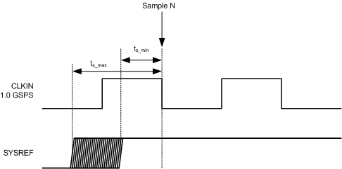
| tSU_SYSREF | Setup time for SYSREF, referenced to the input clock falling edge | 300 | 900 | ps | ||
| tH_SYSREF | Hold time for SYSREF, referenced to the input clock falling edge | 100 | ps | |||
| JESD OUTPUT INTERFACE TIMING CHARACTERISTICS | ||||||
| Unit interval | 100 | 400 | ps | |||
| Serial output data rate | 2.5 | 10 | Gbps | |||
| Total jitter for BER of 1E-15 and lane rate = 10 Gbps | 26 | ps | ||||
| Random jitter for BER of 1E-15 and lane rate = 10 Gbps | 0.75 | ps rms | ||||
| Deterministic jitter for BER of 1E-15 and lane rate = 10 Gbps | 12 | ps, pk-pk | ||||
| tR, tF | Data rise time, data fall time: rise and fall times are measured from 20% to 80%, differential output waveform, 2.5 Gbps ≤ bit rate ≤ 10 Gbps | 35 | ps | |||
(1) Overall latency = latency + tPDI.
 Figure 7-1 SYSREF Timing
 Figure 7-2 Sample
Timing Requirements