ZHCSLR7B March 2021 – September 2024 ADS7067
PRODUCTION DATA
- 1
- 1 特性
- 2 应用
- 3 说明
- 4 Pin Configuration and Functions
- 5 Specifications
-
6 Detailed Description
- 6.1 Overview
- 6.2 Functional Block Diagram
- 6.3 Feature Description
- 6.4 Device Functional Modes
- 6.5 ADS7067 Registers
- 7 Application and Implementation
- 8 Device and Documentation Support
- 9 Revision History
- 10Mechanical, Packaging, and Orderable Information
6.3.3 ADC Transfer Function
The ADC output is in straight binary format. The full-scale input range (FSR) of the ADC is determined by the RANGE bit. On power-up, the FSR is 0 V to VREF. When using the 2 x VREF mode (RANGE = 1b), the ADC can measure analog inputs up to two times the voltage reference. Equation 1 can be used to compute the ADC resolution:
Equation 1. 1 LSB = FSR / 2N
where:
- FSR = Full-scale input range of the ADC
- N = 16
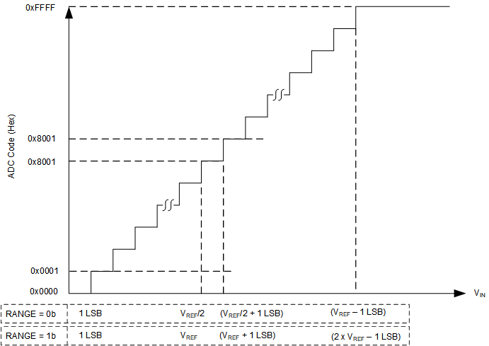
Figure 6-2 and Table 6-1 show the ideal transfer characteristics for this device.
 Figure 6-2 Ideal Transfer Characteristics
Table 6-1 Transfer
Characteristics
| INPUT VOLTAGE | CODE | IDEAL OUTPUT CODE | |
|---|---|---|---|
| RANGE = 0b | RANGE = 1b | ||
| ≤1 LSB | ≤1 LSB | Zero | 0000 |
| 1 LSB to 2 LSBs | 1 LSB to 2 LSBs | Zero + 1 | 0001 |
| (VREF / 2) to (VREF / 2) + 1 LSB | VREF to VREF + 1 LSB | Mid-scale code | 8000 |
| (VREF / 2) + 1 LSB to (VREF / 2) + 2 LSBs | VREF + 1 LSB to VREF + 2 LSBs | Mid-scale code + 1 | 8001 |
| ≥ VREF – 1 LSB | ≥ 2 x VREF – 1 LSB | Full-scale code | FFFF |