ZHCSCL7C May 2014 – April 2021 AFE4403
PRODUCTION DATA
- 1 特性
- 2 应用
- 3 说明
- 4 Revision History
- 5 Device Family Options
- 6 Pin Configuration and Functions
- 7 Specifications
- 8 Detailed Description
- 9 Application Information Disclaimer
- 10Power Supply Recommendations
- 11Layout
- 12Device and Documentation Support
- 13Mechanical, Packaging, and Orderable Information
8.3.5.4 LED Configurations
Multiple LED configurations are possible with the AFE4403.
Case 1: Red, IR LEDs in the common anode configuration for SPO2 and a Green LED for the HRM. Figure 8-21 shows the common anode configuration for this case. Figure 8-22 shows the configuration for HRM mode.
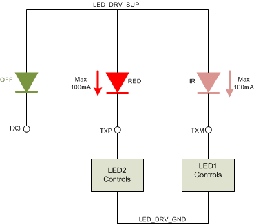 Figure 8-21 SPO2 Application, Common Anode Configuration
HRM mode: Set TX3_MODE = 1.
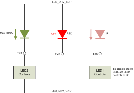 Figure 8-22 HRM Application Using the Third LED (Optional use of the IR LED)
Case 2: Red, IR LEDs in an H-bridge configuration for SPO2 and a Green LED for the HRM. The H-bridge configuration for this case is shown in Figure 8-23. Figure 8-24 shows the configuration for HRM mode.
SPO2 mode: Set TX3_MODE = 0.
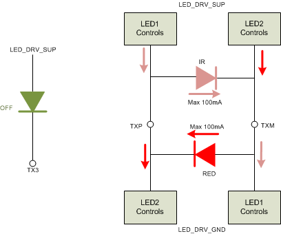 Figure 8-23 SPO2 Application, H-Bridge Configuration
HRM mode: Set TX3_MODE = 1.
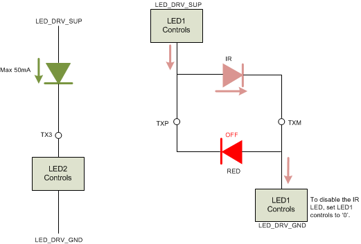 Figure 8-24 HRM Application Using the Third LED
Case 3: Driving two LEDs simultaneously for HRM.
Some sensor modules have two LEDs on either side of the photodiode to make the illumination more uniform. The two LEDs can be connected in parallel, as shown in Figure 8-25.
The connection shown in Figure 8-25 results in an equal split of the current between the two LEDs if their forward voltages are exactly matched. High mismatch in the forward voltages of the two LEDs can cause one of them to consume the majority of the current.
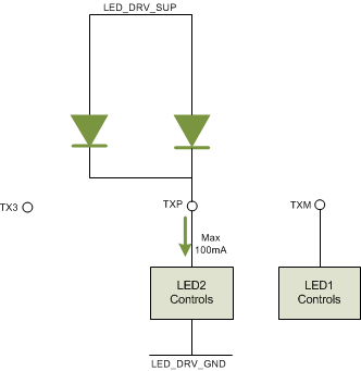 Figure 8-25 Using Two Parallel LEDs for an HRM Application
Case 4: Driving two LEDs separated in time for HRM.
The two LEDs can also be driven as shown in Figure 8-26.
While this mode of driving the two LEDs does not drive them simultaneously, there are two advantages in this case. First, the full current is available for driving each LED. Secondly, the mismatch in the forward voltages between the two LEDs does not play a role.
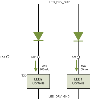 Figure 8-26 Using Two Parallel LEDs for an HRM Application with Separation in Timing