ZHCSCL7C May 2014 – April 2021 AFE4403
PRODUCTION DATA
- 1 特性
- 2 应用
- 3 说明
- 4 Revision History
- 5 Device Family Options
- 6 Pin Configuration and Functions
- 7 Specifications
- 8 Detailed Description
- 9 Application Information Disclaimer
- 10Power Supply Recommendations
- 11Layout
- 12Device and Documentation Support
- 13Mechanical, Packaging, and Orderable Information
8.4.1 ADC Operation and Averaging Module
After the falling edge of the ADC reset signal, the ADC conversion phase starts (refer to Figure 8-14). Each ADC conversion takes 50 µs.
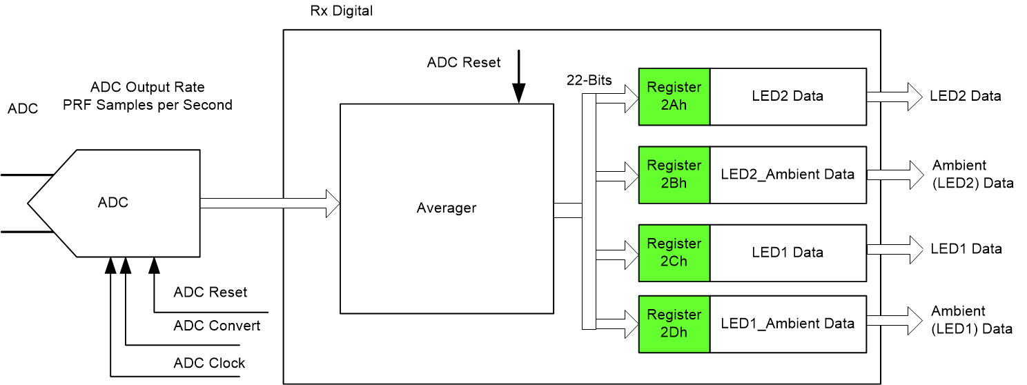
The ADC operates with averaging. The averaging module averages multiple ADC samples and reduces noise to improve dynamic range. Figure 8-27 shows a diagram of the averaging module. The ADC output is a 22-bit code that is obtained by discarding the two MSBs of the 24-bit registers (for example the register with address 2Ah), as shown in Table 8-3.
 Figure 8-27 Averaging
Module
Figure 8-27 Averaging
ModuleTable 8-3 22-Bit Word
| 23 | 22 | 21 | 20 | 19 | 18 | 17 | 16 | 15 | 14 | 13 | 12 |
| Ignore | 22-Bit ADC Code, MSB to LSB | ||||||||||
| 11 | 10 | 9 | 8 | 7 | 6 | 5 | 4 | 3 | 2 | 1 | 0 |