ZHCSCL7C May 2014 – April 2021 AFE4403
PRODUCTION DATA
- 1 特性
- 2 应用
- 3 说明
- 4 Revision History
- 5 Device Family Options
- 6 Pin Configuration and Functions
- 7 Specifications
- 8 Detailed Description
- 9 Application Information Disclaimer
- 10Power Supply Recommendations
- 11Layout
- 12Device and Documentation Support
- 13Mechanical, Packaging, and Orderable Information
8.3.1.4 Receiver Timing
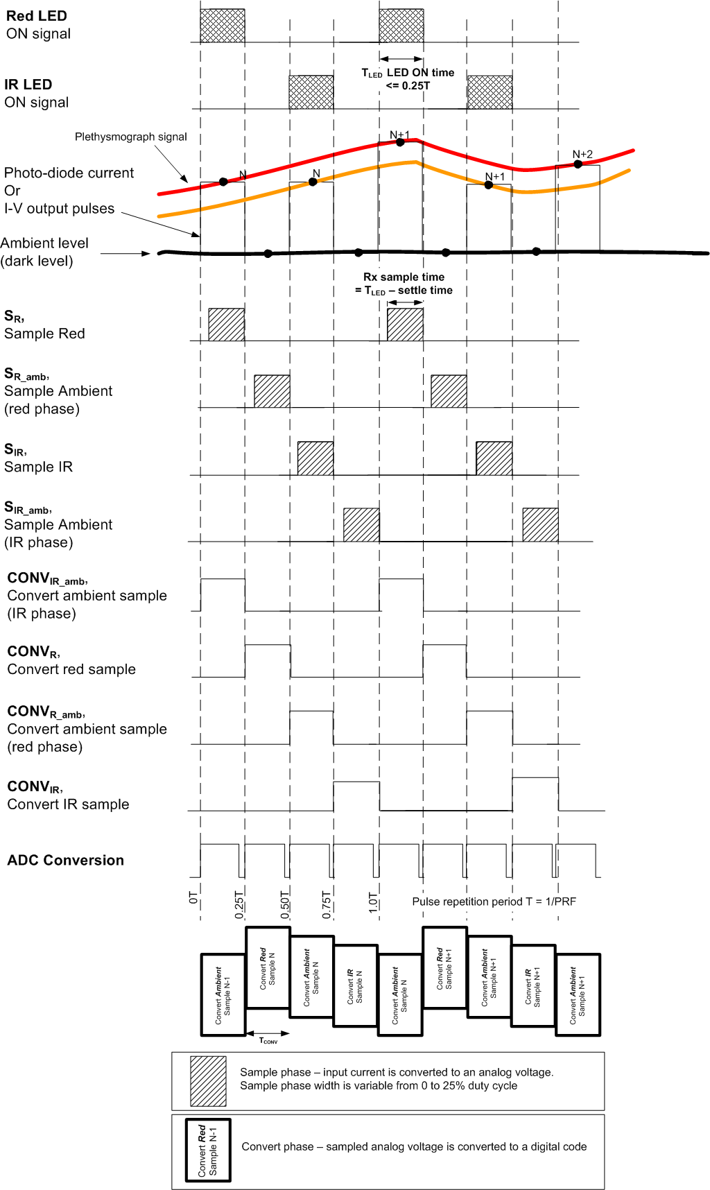
See Figure 8-6 for a timing diagram detailing the control signals related to the LED on-time, Rx sample time, and the ADC conversion times for each channel. Figure 8-6 shows the timing for a case where each phase occupies 25% of the pulse repetition period. However, this percentage is not a requirement. In cases where the device is operated with low pulse repetition frequency (PRF) or low LED pulse durations, the active portion of the pulse repetition period can be reduced. Using the dynamic power-down feature, the overall power consumption can be significantly reduced.

NOTE: Relationship to the AFE4403 EVM is: LED1 = IR and LED2 = RED.
Figure 8-6 Rx Timing Diagram