ZHCSDC3D June 2014 – September 2016 AM4372 , AM4376 , AM4377 , AM4378 , AM4379
PRODUCTION DATA.
- 1器件概述
- 2修订历史记录
- 3Device Comparison
-
4Terminal Configuration and Functions
- 4.1
Pin Diagrams
- ZDN Ball Map [Section Top Left - Top View]
- Table 4-1 ZDN Ball Map [Section Top Middle - Top View]
- Table 4-2 ZDN Ball Map [Section Top Right - Top View]
- Table 4-3 ZDN Ball Map [Section Middle Left - Top View]
- ZDN Ball Map [Section Middle Middle - Top View]
- ZDN Ball Map [Section Middle Right - Top View]
- Table 4-4 ZDN Ball Map [Section Bottom Left - Top View]
- Table 4-5 ZDN Ball Map [Section Bottom Middle - Top View]
- Table 4-6 ZDN Ball Map [Section Bottom Right - Top View]
- 4.2 Pin Attributes
- 4.3
Signal Descriptions
- 4.3.1 ADC Interfaces
- 4.3.2 CAN Interfaces
- 4.3.3 Camera (VPFE) Interfaces
- 4.3.4 Debug Subsystem Interface
- 4.3.5 Display Subsystem (DSS) Interface
- 4.3.6 Ethernet (GEMAC_CPSW) Interfaces
- 4.3.7 External Memory Interfaces
- 4.3.8 General Purpose IOs
- 4.3.9 HDQ Interface
- 4.3.10 I2C Interfaces
- 4.3.11 McASP Interfaces
- 4.3.12 Miscellaneous
- 4.3.13 PRU-ICSS0 Interface
- 4.3.14 PRU-ICSS1 Interface
- 4.3.15 QSPI Interface
- 4.3.16 RTC Subsystem Interface
- 4.3.17 Removable Media Interfaces
- 4.3.18 SPI Interfaces
- 4.3.19 Timer Interfaces
- 4.3.20 UART Interfaces
- 4.3.21 USB Interfaces
- 4.3.22 eCAP Interfaces
- 4.3.23 eHRPWM Interfaces
- 4.3.24 eQEP Interfaces
- 4.1
Pin Diagrams
-
5Specifications
- 5.1 Absolute Maximum Ratings
- 5.2 ESD Ratings
- 5.3 Power-On Hours (POH)
- 5.4 Operating Performance Points
- 5.5 Recommended Operating Conditions
- 5.6 Power Consumption Summary
- 5.7 DC Electrical Characteristics
- 5.8 ADC0: Touch Screen Controller and Analog-to-Digital Subsystem Electrical Parameters
- 5.9 ADC1: Analog-to-Digital Subsystem Electrical Parameters
- 5.10 VPP Specifications for One-Time Programmable (OTP) eFuses
- 5.11 Thermal Resistance Characteristics
- 5.12 External Capacitors
- 5.13
Timing and Switching Characteristics
- 5.13.1 Power Supply Sequencing
- 5.13.2
Clock
- 5.13.2.1 PLLs
- 5.13.2.2 Input Clock Specifications
- 5.13.2.3 Input Clock Requirements
- 5.13.2.4 Output Clock Specifications
- 5.13.2.5 Output Clock Characteristics
- 5.13.3 Timing Parameters and Board Routing Analysis
- 5.13.4 Recommended Clock and Control Signal Transition Behavior
- 5.13.5 Controller Area Network (CAN)
- 5.13.6 DMTimer
- 5.13.7
Ethernet Media Access Controller (EMAC) and Switch
- 5.13.7.1
Ethernet MAC and Switch Electrical Data and Timing
- Table 5-23 Ethernet MAC and Switch Timing Conditions
- 5.13.7.1.1 Ethernet MAC/Switch MDIO Electrical Data and Timing
- 5.13.7.1.2
Ethernet MAC and Switch MII Electrical Data and Timing
- Table 5-27 Timing Requirements for GMII[x]_RXCLK - MII Mode
- Table 5-28 Timing Requirements for GMII[x]_TXCLK - MII Mode
- Table 5-29 Timing Requirements for GMII[x]_RXD[3:0], GMII[x]_RXDV, and GMII[x]_RXER - MII Mode
- Table 5-30 Switching Characteristics for GMII[x]_TXD[3:0], and GMII[x]_TXEN - MII Mode
- 5.13.7.1.3 Ethernet MAC and Switch RMII Electrical Data and Timing
- 5.13.7.1.4
Ethernet MAC and Switch RGMII Electrical Data and Timing
- Table 5-34 Timing Requirements for RGMII[x]_RCLK - RGMII Mode
- Table 5-35 Timing Requirements for RGMII[x]_RD[3:0], and RGMII[x]_RCTL - RGMII Mode
- Table 5-36 Switching Characteristics for RGMII[x]_TCLK - RGMII Mode
- Table 5-37 Switching Characteristics for RGMII[x]_TD[3:0], and RGMII[x]_TCTL - RGMII Mode
- 5.13.7.1
Ethernet MAC and Switch Electrical Data and Timing
- 5.13.8
External Memory Interfaces
- 5.13.8.1 General-Purpose Memory Controller (GPMC)
- 5.13.8.2
Memory Interface
- 5.13.8.2.1
DDR3 and DDR3L Routing Guidelines
- 5.13.8.2.1.1 Board Designs
- 5.13.8.2.1.2 DDR3 Device Combinations
- 5.13.8.2.1.3
DDR3 Interface
- 5.13.8.2.1.3.1 DDR3 Interface Schematic
- 5.13.8.2.1.3.2 Compatible JEDEC DDR3 Devices
- 5.13.8.2.1.3.3 DDR3 PCB Stackup
- 5.13.8.2.1.3.4 DDR3 Placement
- 5.13.8.2.1.3.5 DDR3 Keepout Region
- 5.13.8.2.1.3.6 DDR3 Bulk Bypass Capacitors
- 5.13.8.2.1.3.7 DDR3 High-Speed Bypass Capacitors
- 5.13.8.2.1.3.8 DDR3 Net Classes
- 5.13.8.2.1.3.9 DDR3 Signal Termination
- 5.13.8.2.1.3.10 DDR3 DDR_VREF Routing
- 5.13.8.2.1.3.11 DDR3 VTT
- 5.13.8.2.1.4 DDR3 CK and ADDR_CTRL Topologies and Routing Definition
- 5.13.8.2.1.5 Data Topologies and Routing Definition
- 5.13.8.2.1.6 Routing Specification
- 5.13.8.2.2
LPDDR2 Routing Guidelines
- 5.13.8.2.2.1 LPDDR2 Board Designs
- 5.13.8.2.2.2 LPDDR2 Device Configurations
- 5.13.8.2.2.3
LPDDR2 Interface
- 5.13.8.2.2.3.1 LPDDR2 Interface Schematic
- 5.13.8.2.2.3.2 Compatible JEDEC LPDDR2 Devices
- 5.13.8.2.2.3.3 LPDDR2 PCB Stackup
- 5.13.8.2.2.3.4 LPDDR2 Placement
- 5.13.8.2.2.3.5 LPDDR2 Keepout Region
- 5.13.8.2.2.3.6 LPDDR2 Net Classes
- 5.13.8.2.2.3.7 LPDDR2 Signal Termination
- 5.13.8.2.2.3.8 LPDDR2 DDR_VREF Routing
- 5.13.8.2.2.4 Routing Specification
- 5.13.8.2.1
DDR3 and DDR3L Routing Guidelines
- 5.13.9 Display Subsystem (DSS)
- 5.13.10 Camera (VPFE)
- 5.13.11 Inter-Integrated Circuit (I2C)
- 5.13.12 Multichannel Audio Serial Port (McASP)
- 5.13.13 Multichannel Serial Port Interface (McSPI)
- 5.13.14 Quad Serial Port Interface (QSPI)
- 5.13.15 HDQ/1-Wire Interface (HDQ/1-Wire)
- 5.13.16
Programmable Real-Time Unit Subsystem and Industrial Communication Subsystem (PRU-ICSS)
- 5.13.16.1
Programmable Real-Time Unit (PRU-ICSS PRU)
- Table 5-100 PRU-ICSS PRU Timing Conditions
- 5.13.16.1.1 PRU-ICSS PRU Direct Input/Output Mode Electrical Data and Timing
- 5.13.16.1.2 PRU-ICSS PRU Parallel Capture Mode Electrical Data and Timing
- 5.13.16.1.3 PRU-ICSS PRU Shift Mode Electrical Data and Timing
- 5.13.16.1.4 PRU-ICSS Sigma Delta Electrical Data and Timing
- 5.13.16.1.5 PRU-ICSS ENDAT Electrical Data and Timing
- 5.13.16.2
PRU-ICSS EtherCAT (PRU-ICSS ECAT)
- Table 5-109 PRU-ICSS ECAT Timing Conditions
- 5.13.16.2.1
PRU-ICSS ECAT Electrical Data and Timing
- Table 5-110 PRU-ICSS ECAT Timing Requirements - Input Validated With LATCH_IN
- Table 5-111 PRU-ICSS ECAT Timing Requirements - Input Validated With SYNCx
- Table 5-112 PRU-ICSS ECAT Timing Requirements - Input Validated With Start of Frame (SOF)
- Table 5-113 PRU-ICSS ECAT Timing Requirements - LATCHx_IN
- Table 5-114 PRU-ICSS ECAT Switching Requirements - Digital IOs
- 5.13.16.3 PRU-ICSS MII_RT and Switch
- 5.13.16.4 PRU-ICSS Universal Asynchronous Receiver Transmitter (PRU-ICSS UART)
- 5.13.16.1
Programmable Real-Time Unit (PRU-ICSS PRU)
- 5.13.17
Multimedia Card (MMC) Interface
- 5.13.17.1
MMC Electrical Data and Timing
- Table 5-125 MMC Timing Conditions
- Table 5-126 Timing Requirements for MMC[0]_CMD and MMC[0]_DAT[7:0]
- Table 5-127 Timing Requirements for MMC[1/2]_CMD and MMC[1/2]_DAT[7:0]
- Table 5-128 Switching Characteristics for MMC[x]_CLK
- Table 5-129 Switching Characteristics for MMC[x]_CMD and MMC[x]_DAT[7:0]—HSPE=0
- Table 5-130 Switching Characteristics for MMC[x]_CMD and MMC[x]_DAT[7:0]—HSPE=1
- 5.13.17.1
MMC Electrical Data and Timing
- 5.13.18 Universal Asynchronous Receiver/Transmitter (UART)
- 5.14 Emulation and Debug
- 6Device and Documentation Support
- 7Mechanical, Packaging, and Orderable Information
5.13.9.1.2.1 DSS—Parallel Interface—RFBI Mode—MIPI DBI 2.0—LCD Panel
The Remote Frame Buffer Interface (RFBI) module provides the necessary control signals and data (MIPI® DBI 2.0 type B protocol) to interface to the LCD driver of the LCD panel.
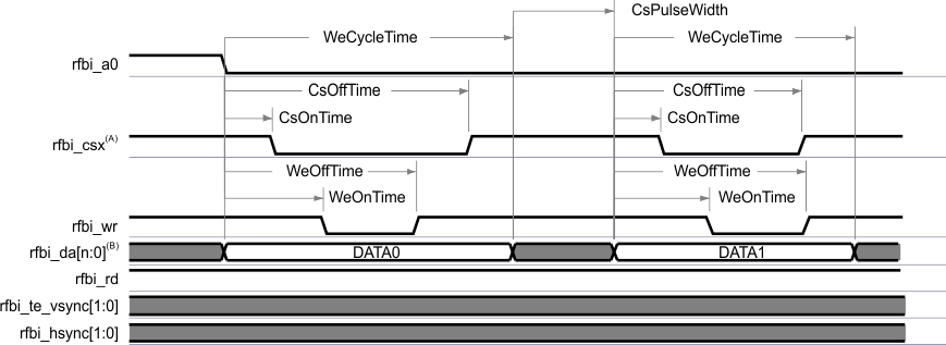
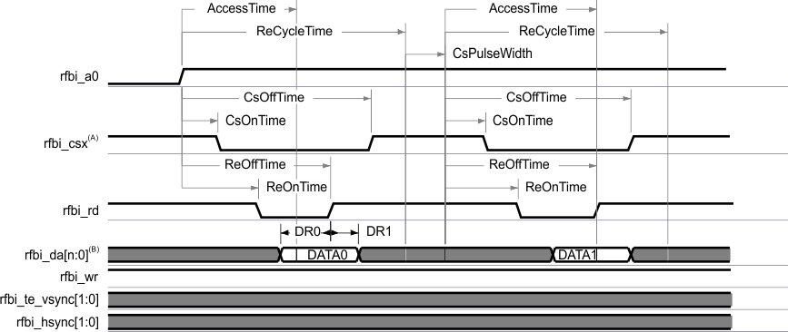
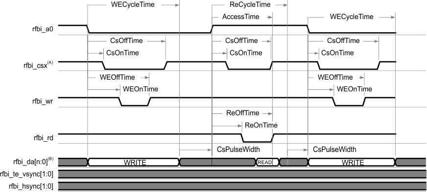
Table 5-76 and Table 5-77 assume testing over the recommended operating conditions and electrical characteristic conditions below (see Figure 5-95, Figure 5-96, and Figure 5-97).
Table 5-75 DSS Timing Conditions—RFBI Mode—MIPI DBI 2.0—LCD Panel(1)
| TIMING CONDITION PARAMETER | VALUE | UNIT | ||
|---|---|---|---|---|
| MIN | MAX | |||
| Input Conditions | ||||
| tR | Input signal rise time | 7 | ns | |
| tF | Input signal fall time | 7 | ns | |
| Output Condition | ||||
| CLOAD | Output load capacitance | 30 | pF | |
(1) For any information regarding the RFBI registers configuration, see the Display Subsystem / Display Subsystem Environment / LCD Support / Parallel Interface / Parallel Interface in RFBI Mode (MIPI DBI Protocol) / Transaction Timing Diagrams section of the AM437x Sitara Processors Technical Reference Manual.
Table 5-76 DSS Timing Requirements—RFBI Mode—MIPI DBI 2.0—LCD Panel
| NO. | PARAMETER | OPP100 | OPP50 | UNIT | |||
|---|---|---|---|---|---|---|---|
| MIN | MAX | MIN | MAX | ||||
| DR0 | tsu(dV-rdH) | Setup time, input data rfbi_da[15:0] valid to output read enable rfbi_rd high | 7 | 7 | ns | ||
| DR1 | th(rdH-dIV) | Hold time, output read enable rfbi_rd high to input data rfbi_da[15:0] invalid | 5 | 5 | ns | ||
| td(Data sampled) | Input data rfbi_da[15:0] sampled at the end of the access time | N(1) | N(1) | ns | |||
- N = (AccessTime) × (TimeParaGranularity + 1) × L4CLK
Table 5-77 DSS Switching Characteristics—RFBI Mode—MIPI DBI 2.0—LCD Panel
| PARAMETER | OPP100 | OPP50 | UNIT | |||
|---|---|---|---|---|---|---|
| MIN | MAX | MIN | MAX | |||
| tw(wrH) | Pulse duration, output write enable rfbi_wr high | A(1) | A(1) | ns | ||
| tw(wrL) | Pulse duration, output write enable rfbi_wr low | B(2) | B(2) | ns | ||
| td(a0-wrL) | Delay time, output command/data control rfbi_a0 transition to output write enable rfbi_wr low | C(3) | C(3) | ns | ||
| td(wrH-a0) | Delay time, output write enable rfbi_wr high to output command/data control rfbi_a0 transition | D(4) | D(4) | ns | ||
| td(csx-wrL) | Delay time, output chip select rfbi_csx(14) low to output write enable rfbi_wr low | E(5) | E(5) | ns | ||
| td(wrH-csxH) | Delay time, output write enable rfbi_wr high to output chip select rfbi_csx(14) high | F(6) | F(6) | ns | ||
| td(dV) | Output data rfbi_da[15:0] valid | G(7) | G(7) | ns | ||
| td(a0H-rdL) | Delay time, output command/data control rfbi_a0 high to output read enable rfbi_rd low | H(8) | H(8) | ns | ||
| td(rdlH-a0) | Delay time, output read enable rfbi_rd high to output command/data control rfbi_a0 transition | I(9) | I(9) | ns | ||
| tw(rdH) | Pulse duration, output read enable rfbi_rd high | J(10) | J(10) | ns | ||
| tw(rdL) | Pulse duration, output read enable rfbi_rd low | K(11) | K(11) | ns | ||
| td(rdL-csxL) | Delay time, output read enable rfbi_rd low to output chip select rfbi_csx(14) low | L(12) | L(12) | ns | ||
| td(rdH-csxH) | Delay time, output read enable rfbi_rd high to output chip select rfbi_csx(14) high | M(13) | M(13) | ns | ||
| tR(wr) | Rise time, output write enable rfbi_wr | 7 | 7 | ns | ||
| tF(wr) | Fall time, output write enable rfbi_wr | 7 | 7 | ns | ||
| tR(a0) | Rise time, output command/data control rfbi_a0 | 7 | 7 | ns | ||
| tF(a0) | Fall time, output command/data control rfbi_a0 | 7 | 7 | ns | ||
| tR(csx) | Rise time, output chip select rfbi_csx(14) | 7 | 7 | ns | ||
| tF(csx) | Fall time, output chip select rfbi_csx(14) | 7 | 7 | ns | ||
| tR(d) | Rise time, output data rfbi_da[15:0] | 7 | 7 | ns | ||
| tF(d) | Fall time, output data rfbi_da[15:0] | 7 | 7 | ns | ||
| tR(rd) | Rise time, output read enable rfbi_rd | 7 | 7 | ns | ||
| tF(rd) | Fall time, output read enable rfbi_rd | 7 | 7 | ns | ||
- A = (WECycleTime – WEOffTime) × (TimeParaGranularity + 1) × L4CLK
- B = (WEOffTime – WEOntime) × (TimeParaGranularity + 1) × L4CLK
- C = WEOnTime × (TimeParaGranularity + 1) × L4CLK
- D = (WECycleTime + CSPulseWidth – WEOffTime) × (TimeParaGranularity + 1) × L4CLK if mode Write to Read or Read to Write is enabled
- E = (WEOnTime – CSOnTime) × (TimeParaGranularity + 1) × L4CLK
- F = (CSOffTime – WEOffTime) × (TimeParaGranularity + 1) × L4CLK
- G = WECycleTime × (TimeParaGranularity + 1) × L4CLK
- H = REOnTime × (TimeParaGranularity + 1) × L4CLK
- I = (RECycleTime + CSPulseWidth – REOffTime) × (TimeParaGranularity + 1) × L4CLK if mode Write to Read or Read to Write is enabled
- J = (RECycleTime – REOffTime) × (TimeParaGranularity + 1) × L4CLK
- K = (REOffTime – REOntime) × (TimeParaGranularity + 1) × L4CLK
- L = (REOnTime – CSOnTime) × (TimeParaGranularity + 1) × L4CLK
- M = (CSOffTime – REOffTime) × (TimeParaGranularity + 1) × L4CLK
- In rfbi_csx, x is equal to 0 or 1.

A. In rfbi_csx, x is equal to 0 or 1.
B. rfbi_da[n:0], n up to 15
C. For more information, see the DSS chapter in the AM437x Sitara Processors Technical Reference Manual.
Figure 5-95 DSS—RFBI Mode—MIPI DBI 2.0—LCD Panel—Command / Data Write

A. In rfbi_csx, x is equal to 0 or 1.
B. rfbi_da[n:0], n up to 15
C. For more information, see the DSS chapter in the AM437x Sitara Processors Technical Reference Manual.
Figure 5-96 DSS—RFBI Mode—MIPI DBI 2.0—LCD Panel—Command / Data Read

A. In rfbi_csx, x is equal to 0 or 1.
B. rfbi_da[n:0], n up to 15
C. For more information, see the DSS chapter in the AM437x Sitara Processors Technical Reference Manual.
Figure 5-97 DSS—RFBI Mode—MIPI DBI 2.0—LCD Panel—Command / Data Write to Read and Read to Write Modes