ZHCSDL7B November 2014 – March 2016 AMC7834
PRODUCTION DATA.
- 1 特性
- 2 应用范围
- 3 说明
- 4 修订历史记录
- 5 Pin Configuration and Functions
-
6 Specifications
- 6.1 Absolute Maximum Ratings
- 6.2 ESD Ratings
- 6.3 Recommended Operating Conditions
- 6.4 Thermal Information
- 6.5 Electrical Characteristics—DAC Specifications
- 6.6 Electrical Characteristics—ADC, Current and Temperature Sensor Specifications
- 6.7 Electrical Characteristics—General Specifications
- 6.8 Serial Interface Timing Requirements
- 6.9 Switching Characteristics—DAC Specifications
- 6.10 Switching Characteristics—ADC, Current and Temperature Sensor Specifications
- 6.11 Switching Characteristics—General Specifications
- 6.12 Typical Characteristics
-
7 Detailed Description
- 7.1 Overview
- 7.2 Functional Block Diagram
- 7.3 Feature Description
- 7.4 Device Functional Modes
- 7.5 Programming
- 7.6
Register Maps
- 7.6.1 Power Mode: Address 0x02
- 7.6.2 Device Identification: Address 0x04 through 0x0C
- 7.6.3
General Device Configuration: Address 0x10 through 0x16
- 7.6.3.1 AMC Configuration 0 Register (address = 0x10) [reset = 0x0300]
- 7.6.3.2 AMC Configuration 1 Register (address = 0x11) [reset = 0x036A]
- 7.6.3.3 ADC MUX Register (address = 0x12) [reset = 0x0000]
- 7.6.3.4 Closed Loop Settling Time Register (address = 0x14) [reset = 0x2222]
- 7.6.3.5 DAC Sync Register (address = 0x15) [reset = 0x0000]
- 7.6.3.6 DAC Range Register (address = 0x16) [reset = 0x0000]
- 7.6.4
Clamp and Alarm Configuration: Address 0x17 through 0x1B
- 7.6.4.1 CLAMP Configuration Register (address = 0x17) [reset = 0x003F]
- 7.6.4.2 SLEEP1 Configuration Register (address = 0x18) [reset = 0xFF00]
- 7.6.4.3 SLEEP2 Configuration Register (address = 0x19) [reset = 0xFF00]
- 7.6.4.4 ALARMOUT Clamp Register (address = 0x1A) [reset = 0x0000]
- 7.6.4.5 ALARMOUT Configuration Register (address = 0x1B) [reset = 0x0000]
- 7.6.5 Conversion Trigger: Address 0x1C
- 7.6.6 Reset: Address 0x1D
- 7.6.7 Device Status: Address 0x1E and 0x1F
- 7.6.8
ADC Data: Address 0x20 through 0x2F
- 7.6.8.1 ADCn-Internal-Data Register (address = 0x20 to 0x23) [reset = 0x0000]
- 7.6.8.2 ADCn-External-Data Register (address = 0x24 to 0x27) [reset = 0x0000]
- 7.6.8.3 CSn-Data Register (address = 0x28 to 0x2B) [reset = 0x0000]
- 7.6.8.4 LT-Data Register (address = 0x2D) [reset = 0x0000]
- 7.6.8.5 RTn-Data Register (address = 0x2E to 0x2F) [reset = 0x0000]
- 7.6.9 DAC Data: Address 0x30 through 0x37
- 7.6.10 Closed-Loop Control: Address 0x38 through 0x3B
- 7.6.11
Alarm Threshold Configuration: Address 0x40 through 0x4F
- 7.6.11.1 ADCINTn/CSn-Upper-Threshold Register (address = 0x40, 0x42, 0x44 and 0x46) [reset = 0x0FFF]
- 7.6.11.2 ADCINTn/CSn-Lower-Threshold Register (address = 0x41, 0x43, 0x45 and 0x47) [reset = 0x0000]
- 7.6.11.3 TS-Upper-Threshold Register (address = 0x48, 0x4A and 0x4C) [reset = 0x07FF]
- 7.6.11.4 TS-Lower-Threshold Register (address = 0x49, 0x4B and 0x4D) [reset = 0x0800]
- 7.6.11.5 DACnn-Upper-Threshold Register (address = 0x4E and 0x4F) [reset = 0x0FFF]
- 7.6.12 Alarm Hysteresis Configuration: Address 0x50 and 0x56
- 7.6.13 GPIO: Address 0x58
- 8 Application and Implementation
- 9 Power Supply Recommendations
- 10Layout
- 11器件和文档支持
- 12机械、封装和可订购信息
6 Specifications
6.1 Absolute Maximum Ratings
over operating free-air temperature range (unless otherwise noted)(1)| MIN | MAX | UNIT | ||
|---|---|---|---|---|
| Supply voltage | AVDD to GND | –0.3 | 6 | V |
| DVDD to GND | –0.3 | 6 | ||
| IOVDD to GND | –0.3 | 6 | ||
| AVCC to GND | –0.3 | 13 | ||
| AVSS to GND | –6 | 0.3 | ||
| PAVDD to AVSS | –0.3 | 26 | ||
| DGND to AGND | –0.3 | 0.3 | ||
| Pin voltage | ADC analog input voltage to GND | –0.3 | AVDD + 0.3 | V |
| Current sense input voltage to GND | –0.3 | 65 | ||
| Bipolar DAC outputs to GND | AVSS – 0.3 | AVDD + 0.3 | ||
| Auxiliary DAC outputs to GND | –0.3 | AVCC + 0.3 | ||
| VCLAMP1, VCLAMP2 inputs to GND | –0.3 | AVDD + 0.3 | ||
| D1+, D1–, D2+ and D2– to GND | –0.3 | AVDD + 0.3 | ||
| REF_CMP, REF_IN to GND | –0.3 | AVDD + 0.3 | ||
| REF_OUT to GND | –0.3 | AVDD + 0.3 | ||
| PA_ON to GND | –0.3 | PAVDD + 0.3 | ||
| CS, SCLK, SDI, DACTRIG, RESET, SLEEP1, SLEEP2 and DAV/ADC_RDY to GND | –0.3 | IOVDD + 0.3 | ||
| SDO to GND | –0.3 | IOVDD + 0.3 | ||
| GPIOs, ALARMOUT to GND | –0.3 | 6 | ||
| Pin current | ADC analog input current | –10 | 10 | mA |
| REF_OUT output current | –0.3 | 0.3 | ||
| GPIOs, ALARMOUT sinking current | 5 | |||
| Operating temperature range | –40 | 125 | °C | |
| Junction temperature range, TJ max | –40 | 150 | °C | |
| Storage temperature, Tstg | –40 | 150 | °C | |
(1) Stresses beyond those listed under Absolute Maximum Ratings may cause permanent damage to the device. These are stress ratings only, which do not imply functional operation of the device at these or any other conditions beyond those indicated under Recommended Operating Conditions. Exposure to absolute-maximum-rated conditions for extended periods may affect device reliability.
6.2 ESD Ratings
| VALUE | UNIT | |||
|---|---|---|---|---|
| V(ESD) | Electrostatic discharge | Human body model (HBM), per ANSI/ESDA/JEDEC JS-001(1) | ±750 | V |
| Charged device model (CDM), per JEDEC specification JESD22-C101(2) | ±250 | |||
(1) JEDEC document JEP155 states that 500-V HBM allows safe manufacturing with a standard ESD control process.
(2) JEDEC document JEP157 states that 250-V CDM allows safe manufacturing with a standard ESD control process.
6.3 Recommended Operating Conditions
over operating free-air temperature range (unless otherwise noted)| MIN | NOM | MAX | UNIT | ||
|---|---|---|---|---|---|
| Supply voltage | AVDD(1) | 4.5 | 5 | 5.5 | V |
| DVDD(1) | 4.5 | 5 | 5.5 | ||
| IOVDD | 1.7 | 3.3 | 3.6 | ||
| AVCC | 4.5 | 5 | 12.5 | ||
| AVSS(2) | –5.5 | –5 | 0 | ||
| PAVDD | 4 | 5 | 20 | ||
| Specified performance temperature | –40 | 25 | 105 | °C | |
| Operating temperature | –40 | 25 | 125 | °C | |
(1) The value of the DVDD pin must be equal to that of the AVDD pins.
(2) The value of the AVSS pin is only equal to AGND when all bipolar DACs are set to operate in positive voltage ranges.
6.4 Thermal Information
| THERMAL METRIC(1)(2) | RTQ (VQFN) | UNIT | |
|---|---|---|---|
| 56 PINS | |||
| RθJA | Junction-to-ambient thermal resistance | 24.7 | °C/W |
| RθJC(top) | Junction-to-case (top) thermal resistance | 7.9 | |
| RθJB | Junction-to-board thermal resistance | 2.7 | |
| ψJT | Junction-to-top characterization parameter | 0.2 | |
| ψJB | Junction-to-board characterization parameter | 2.7 | |
| RθJC(bot) | Junction-to-case (bottom) thermal resistance | 0.3 | |
(1) For more information about traditional and new thermal metrics, see the IC Package Thermal Metrics application report, SPRA953.
(2) TI strongly recommends to solder the device thermal pad to a board plane connected to the AVSS pin.
6.5 Electrical Characteristics—DAC Specifications
The electrical ratings specified in this section apply to all specifications in this document, unless otherwise noted. These specifications are interpreted as conditions that do not degrade the device parametric or functional specifications for the life of the product containing it. AVDD = DVDD = 5 V, AVCC = 5 V, AVSS = –5 V, IOVDD = 3.3 V, PAVDD = 5 V, AGND = DGND = 0 V, external 2.5 V reference, DAC output range = 0 to 5 V for all DACs, no load on the DACs, current sense inputs common mode at 48 V, TA = –40°C to +105°C| PARAMETER | TEST CONDITIONS | MIN | TYP | MAX | UNIT | |
|---|---|---|---|---|---|---|
| BIPOLAR DAC DC ACCURACY | ||||||
| Resolution | 12 | Bits | ||||
| INL | Relative accuracy | Measured by line passing through codes 040h and FC0h. 0 to 5 V range | ±0.3 | ±1 | LSB | |
| Measured by line passing through codes 040h and FC0h. –4 to 1 V and –5 to 0 V ranges | ±0.3 | ±1 | ||||
| DNL | Differential nonlinearity | Specified monotonic. Measured by line passing through codes 040h and FC0h. 0 to 5 V range | ±0.05 | ±1 | LSB | |
| Specified monotonic. Measured by line passing through codes 040h and FC0h. –4 to 1 V and –5 to 0 V ranges | ±0.05 | ±1 | ||||
| TUE | Total unadjusted error | TA = 25°C, 0 to 5 V range | ±1 | ±15 | mV | |
| TA = 25°C, –4 to 1 V and –5 to 0 V ranges | ±2 | ±15 | ||||
| Offset error | TA = 25°C. Measured by line passing through codes 040h and FC0h. 0 to 5 V range | ±0.2 | ±10 | mV | ||
| Zero-code error | TA = 25°C. Code 000h. –4 to 1 V and –5 to 0 V ranges. AVSS = –5.5 V | ±2 | ±10 | mV | ||
| Gain error | TA = 25°C. Measured by line passing through codes 040h and FC0h. 0 to 5 V range | ±0.02 | ±0.2 | %FSR | ||
| TA = 25°C. Measured by line passing through codes 040h and FC0h. –4 to 1 V and –5 to 0 V ranges | ±0.02 | ±0.2 | ||||
| Offset temperature drift | 0 to 5 V range | ±1 | ppm/°C | |||
| Zero-code temperature drift | –4 to 1 V and –5 to 0 V ranges. AVSS = –5.5 V | ±1.5 | ppm/°C | |||
| Gain temperature drift | All output ranges | ±1 | ppm/°C | |||
| AUXILIARY DAC DC ACCURACY | ||||||
| Resolution | 12 | Bits | ||||
| INL | Integral nonlinearity | Measured by line passing through codes 040h and FC0h. 0 to 5 V range | ±0.5 | ±1.25 | LSB | |
| Measured by line passing through codes 040h and FC0h. 2.5 to 7.5 V range. AVCC = 12 V | ±0.5 | ±1.25 | ||||
| DNL | Differential nonlinearity | Specified monotonic. Measured by line passing through codes 040h and FC0h. 0 to 5 V range | ±0.05 | ±1 | LSB | |
| Specified monotonic. Measured by line passing through codes 040h and FC0h. 2.5 to 7.5 V range. AVCC = 12 V | ±0.05 | ±1 | ||||
| TUE | Total unadjusted error | TA = 25°C. 0 to 5 V range | ±2 | ±15 | mV | |
| TA = 25°C. 2.5 to 7.5 V range. AVCC = 12 V | ±2 | ±15 | ||||
| Offset error | TA = 25°C. Measured by line passing through codes 040h and FC0h. 0 to 5 V range | ±0.3 | ±10 | mV | ||
| TA = 25°C. Measured by line passing through codes 040h and FC0h. 2.5 to 7.5 V range. AVCC = 12 V | ±1 | ±10 | ||||
| Gain error | TA = 25°C. Measured by line passing through codes 040h and FC0h. 0 to 5 V range | ±0.03 | ±0.2 | %FSR | ||
| TA = 25°C. Measured by line passing through codes 040h and FC0h. 2.5 to 7.5 V range. AVCC = 12 V | ±0.03 | ±0.2 | ||||
| Offset temperature drift | All output ranges | ±1 | ppm/°C | |||
| Gain temperature drift | All output ranges | ±1 | ppm/°C | |||
| DAC OUTPUT CHARACTERISTICS | ||||||
| Bipolar DAC range(1) | DACn_range set to 00 | –4 | 1 | V | ||
| DACn_range set to 01 | –5 | 0 | ||||
| DACn_range set to 10 | –5 | 0 | ||||
| DACn_range set to 11 | 0 | 5 | ||||
| Auxiliary DAC range(2) | AUXDACn_range set to 0 | 0 | 5 | V | ||
| AUXDACn_range set to 1 | 2.5 | 7.5 | ||||
| Short-circuit current | Bipolar DACs: Full-scale current shorted to AVSS or AVDD
Auxiliary DACs: Full-scale current shorted to AGND or AVCC |
45 | mA | |||
| Load current(3) | Bipolar DACs: Source or sink with 300 mV headroom from AVDD or AVSS, voltage drop < 25 mV Auxiliary DACs: Source or sink with 300 mV headroom from AVCC or AGND, voltage drop < 25 mV |
±10 | mA | |||
| Maximum capacitive load(4) | All DAC outputs. RL = ∞ | 0 | 10 | nF | ||
| DC output impedance | All DAC outputs. Code set to 800h, ±10 mA | 1 | Ω | |||
| Glitch energy | All DAC outputs. Transition: Code 7FFh to 800h; 800h to 7FFh | 1 | nV-s | |||
| Output noise | Auxiliary DACs. 1 kHz, code 800h | 200 | nV/√Hz | |||
| Bipolar DACs. 1 kHz, code 800h | 100 | |||||
| Auxiliary DACs. Integrated noise from 0.1 Hz to 10 Hz, code 800h | 20 | µVPP | ||||
| Bipolar DACs. Integrated noise from 0.1 Hz to 10 Hz, code 800h | 10 | |||||
| CLAMP OUTPUT MODE | ||||||
| VCLAMP [1:2] voltage range | 0 | –AVSS / 3 | V | |||
| VCLAMP [1:2] input current | ±0.5 | µA | ||||
| Clamp output voltage | Bipolar DACs. Clamp voltage = –3 × VCLAMP[1:2] | AVSS | 0 | V | ||
| Auxiliary DACs | AGND | |||||
| Clamp output current | Bipolar DACs. Source, sink, or both with 300-mV headroom from AVSS, voltage drop < 25 mV | ±10 | mA | |||
| Clamp pull-down resistance | Auxiliary DACs. Measured to AGND | 9 | kΩ | |||
| Bipolar DACs. VCLAMP buffers inactive (AVSS clamp mode). Measured to AVSS | 550 | Ω | ||||
(1) The output voltage must not be greater than AVDD or lower than AVSS. A minimum of 100 mV headroom from AVDD is required.
(2) The output voltage must not be greater than AVCC or lower than AGND. A minimum of 100 mV headroom from AVCC is required.
(3) If all channels are simultaneously loaded, care must be taken to ensure the thermal conditions for the device are not exceeded.
(4) To be sampled during initial release to ensure compliance; not subject to production testing.
6.6 Electrical Characteristics—ADC, Current and Temperature Sensor Specifications
The electrical ratings specified in this section apply to all specifications in this document, unless otherwise noted. These specifications are interpreted as conditions that do not degrade the device parametric or functional specifications for the life of the product containing it. AVDD = DVDD = 5 V, AVCC = 5 V, AVSS = –5 V, IOVDD = 1.8 to 3.3 V, PAVDD = 5 V, AGND = DGND = 0 V, external 2.5 V reference, DAC output range = 0 to 5 V for all DACs, no load on the DACs, current sense inputs common mode at 48 V, TA = –40°C to +105°C| PARAMETER | TEST CONDITIONS | MIN | TYP | MAX | UNIT | |
|---|---|---|---|---|---|---|
| EXTERNAL ANALOG INPUTS (ADC1, ADC2, ADC3 and ADC4) | ||||||
| Resolution | 12 | Bits | ||||
| INL | Integral nonlinearity | ±0.5 | ±1 | LSB | ||
| DNL | Differential nonlinearity | Specified monotonic | ±0.5 | ±1 | LSB | |
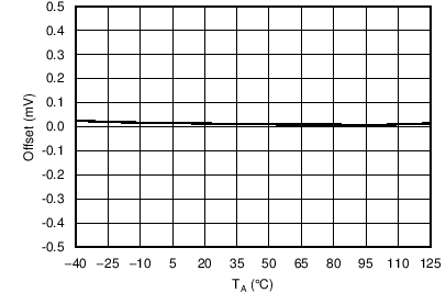
| Offset error | ±0.3 | ±4.5 | LSB | |||
| Offset error match | ±1 | LSB | ||||
| Gain error | ±0.3 | ±4 | LSB | |||
| Gain error match | ±1 | LSB | ||||
| Full-scale input range(1) | 0 | Vref | V | |||
| Input capacitance | 48 | pF | ||||
| DC-input leakage current | Unselected ADC input | ±2 | µA | |||
| INTERNAL MONITORING INPUTS (BIPOLAR DAC-OUTPUT MONITORING) | ||||||
| Full scale input range(1) | –5 | 2.5 | V | |||
| Resolution | LSB size | 1.83 | mV | |||
| CURRENT-SENSE INPUTS | ||||||
| Common mode voltage | 4 | 60 | V | |||
| Full scale sense voltage(1) | SENSEn+ – SENSEn- | 0 | 200 | mV | ||
| Input resistance | Per current sense input terminal | 192 | kΩ | |||
| Gain accuracy | ±0.1% | ±1% | ||||
| Input offset error | CS-FILTER[2:0] = 100 Common mode voltage = 4 V |
±50 | ±500 | µV | ||
| CMRR | CS-FILTER[2:0] = 100 | 80 | dB | |||
| Resolution | LSB size | 48.83 | µV | |||
| TEMPERATURE SENSOR: INTERNAL | ||||||
| Operating range(1)(2) | Specified monotonic over entire range. | –55 | 125 | °C | ||
| Accuracy(2) | TJ = –40°C to 125°C | ±3 | °C | |||
| Resolution | LSB size TJ = –40°C to 125°C |
0.25 | °C | |||
| TEMPERATURE SENSOR: EXTERNAL (USING 2N3906 EXTERNAL TRANSISTOR) | ||||||
| Operating range(1)(2) | –55 | 150 | °C | |||
| Accuracy(2) | RT-SET[2:0] = 011, CS-FILTER[2:0] = 100 TA = –40°C to 125°C, T(DIODE) = –40°C to 150°C |
±3 | °C | |||
| Resolution | LSB size TA = –40°C to 125°C, T(DIODE) = –40°C to 150°C |
0.25 | °C | |||
(1) Input range for all monitoring inputs must be met for accuracy specifications to apply.
(2) Not tested during production. Specified by design and characterization.
6.7 Electrical Characteristics—General Specifications
The electrical ratings specified in this section apply to all specifications in this document, unless otherwise noted. These specifications are interpreted as conditions that do not degrade the device parametric or functional specifications for the life of the product containing it. AVDD = DVDD = 5 V, AVCC = 5 V, AVSS = –5 V, IOVDD = 1.8 to 3.3 V, PAVDD = 5 V, AGND = DGND = 0 V, external 2.5 V reference, DAC output range = 0 to 5 V for all DACs, no load on the DACs, current sense inputs common mode at 48 V, TA = –40°C to 105°C| PARAMETER | TEST CONDITIONS | MIN | TYP | MAX | UNIT | |
|---|---|---|---|---|---|---|
| EXTERNAL REFERENCE INPUT | ||||||
| VREF_IN | Input voltage range | REF_IN pin | 2.5 | V | ||
| Input current | VREF_IN = 2.5 V | 1 | 100 | µA | ||
| DAC reference buffer offset | TA = 25°C | ±5 | mV | |||
| ADC reference buffer offset | TA = 25°C | ±5 | mV | |||
| INTERNAL REFERENCE | ||||||
| Output voltage | TA = 25°C, REF_OUT pin | 2.4925 | 2.5 | 2.5075 | V | |
| Reference temperature coefficient | 10 | 35 | ppm/°C | |||
| Output voltage noise | 1 kHz | 260 | nV/√Hz | |||
| Integrated noise from 0.1 Hz to 10 Hz | 13 | µVPP | ||||
| PA_ON OUTPUT | ||||||
| PA_ON output voltage | PAVDD ≤ 20 V | AGND | PAVDD | V | ||
| SUPPLY ALARMS(1) | ||||||
| AVSS alarm threshold | –4.4 | –4.1 | –3.8 | V | ||
| AVDD alarm threshold | 3.4 | 3.9 | 4.4 | V | ||
| DIGITAL LOGIC(1) | ||||||
| VIH | High-level input voltage | IOVDD = 1.7 V to 3.6 V | 0.7 × IOVDD | V | ||
| VIL | Low-level input voltage | IOVDD = 1.7 V to 3.6 V | 0.3 × IOVDD | V | ||
| Vhys | Hysteresis voltage | IOVDD = 1.7 V to 3.6 V | 0.1 × IOVDD | V | ||
| VOH | High-level output voltage | SDO and DAV/ADC_RDY. IOVDD = 1.7 V, I(LOAD) = 1 mA | IOVDD – 0.4 | V | ||
| VOL | Low-level output voltage | IOVDD = 1.7 V to 3.6 V, I(LOAD) = –1 mA | 0.4 | V | ||
| High impedance leakage | ±0.5 | µA | ||||
| High impedance output capacitance | 10 | pF | ||||
| POWER REQUIREMENTS | ||||||
| IAVDD | AVDD supply current | POWER-MODE = 10. AVDD = DVDD = 5.5 V, AVCC = 5.5 V PAVDD = 20 V, AVSS = –5.5 V, IOVDD = 3.6 V All monitoring channels enabled Bipolar DACs in –5 to 0 V range Auxiliary DACs in 0 to 5 V range All DACs at 800h code. PA_ON in "ON" state |
10 | 12.5 | mA | |
| IAVCC | AVCC supply current | 1.5 | 2 | mA | ||
| IAVSS | AVSS supply current | –3.5 | –2.5 | mA | ||
| IDVDD | DVDD supply current | 2.5 | 3 | mA | ||
| IIOVDD | IOVDD supply current | 1.75 | 2.5 | µA | ||
| IPAVDD | PAVDD supply current | 170 | 250 | µA | ||
| Power consumption | 95 | 120.5 | mW | |||
| IAVDD | AVDD supply current | POWER-MODE = 00. AVDD = DVDD = 5.5 V, AVCC = 5.5 V PAVDD = 20 V, AVSS = –5.5 V, IOVDD = 3.6 V All DACs in clamp mode at 0 V PA_ON in "OFF" state |
3.5 | mA | ||
| IAVCC | AVCC supply current | 0.2 | mA | |||
| IAVSS | AVSS supply current | –2 | mA | |||
| IDVDD | DVDD supply current | 2.5 | mA | |||
| IIOVDD | IOVDD supply current | 1.75 | µA | |||
| IPAVDD | PAVDD supply current | 12 | µA | |||
| Power consumption | 45 | mW | ||||
(1) Not tested during production. Specified by design and characterization.
6.8 Serial Interface Timing Requirements(1)(2)
AVDD = DVDD = 5 V, AVCC = 5 V, AVSS = –5 V, PAVDD = 5 V, AGND = DGND = 0 V, external 2.5 V reference, DAC output range = 0 to 5 V for all DACs, no load on the DACs, current sense inputs common mode at 48 V, TA = –40°C to +105°C (unless otherwise noted)| IOVDD = 1.7 TO 2.7 V | IOVDD = 2.7 TO 3.6 V | UNIT | |||||
|---|---|---|---|---|---|---|---|
| MIN | MAX | MIN | MAX | ||||
| fSCLK | SCLK frequency | 0.2 | 10 | 0.2 | 15 | MHz | |
| tp | SCLK period | See Figure 1 and Figure 2. | 100 | 66.67 | ns | ||
| tPH | SCLK pulse width high | 40 | 26 | ns | |||
| tPL | SCLK pulse width low | 40 | 26 | ns | |||
| tsu | SDI setup | 10 | 10 | ns | |||
| th | SDI hold | 10 | 10 | ns | |||
| t(ODZ) | SDO driven to tri-state | See Figure 2. | 0 | 15 | 0 | 10 | ns |
| t(OZD) | SDO tri-state to driven | 0 | 20 | 0 | 15 | ns | |
| t(OD) | SDO output delay | 0 | 20 | 0 | 15 | ns | |
| tsu(CS) | CS setup | See Figure 1 and Figure 2 | 5 | 5 | ns | ||
| th(CS) | CS hold | 20 | 20 | ns | |||
| t(IAG) | Inter-access gap | 15 | 15 | ns | |||
(1) Specified by design and characterization. Not tested during production.
(2) SDO loaded with 10 pF load capacitance for SDO timing specifications.
6.9 Switching Characteristics—DAC Specifications
The electrical ratings specified in this section apply to all specifications in this document, unless otherwise noted. These specifications are interpreted as conditions that do not degrade the device parametric or functional specifications for the life of the product containing it. AVDD = DVDD = 5 V, AVCC = 5 V, AVSS = –5 V, IOVDD = 3.3 V, PAVDD = 5 V, AGND = DGND = 0 V, external 2.5 V reference, DAC output range = 0 to 5 V for all DACs, no load on the DACs, current sense inputs common mode at 48 V, TA = –40°C to +105°C| PARAMETER | TEST CONDITIONS | MIN | TYP | MAX | UNIT | |
|---|---|---|---|---|---|---|
| DAC OUTPUT CHARACTERISTICS | ||||||
| Output voltage settling time | Transition: Code 400h to C00h to within ½ LSB. RL= 2 kΩ, CL = 200 pF. All DAC outputs. All output ranges |
10 | µs | |||
| Slew rate | Transition: Code 400h to C00h, 10% to 90%. RL= 2 kΩ, CL = 200 pF. All DAC outputs. All output ranges |
1.25 | V/µs | |||
| CLAMP OUTPUT MODE | ||||||
| Clamp shutdown delay(1) | All DAC outputs. RL = ∞, CL = 200 pF, clamp from 3.5 V output, within 10% accuracy of active DAC output, measured from SLEEP 0 to 1 transition | 5 | µs | |||
| Wake-up from clamp delay(1) | All DAC outputs. RL = ∞, CL = 200 pF, wake-up to 3.5 V output, within 10% accuracy of active DAC output, measured from SLEEP 1 to 0 transition | 5 | µs | |||
(1) Not tested during production. Specified by design and characterization.
6.10 Switching Characteristics—ADC, Current and Temperature Sensor Specifications
The electrical ratings specified in this section apply to all specifications in this document, unless otherwise noted. These specifications are interpreted as conditions that do not degrade the device parametric or functional specifications for the life of the product containing it. AVDD = DVDD = 5 V, AVCC = 5 V, AVSS = –5 V, IOVDD = 1.8 to 3.3 V, PAVDD = 5 V, AGND = DGND = 0 V, external 2.5 V reference, DAC output range = 0 to 5 V for all DACs, no load on the DACs, current sense inputs common mode at 48 V, TA = –40°C to +105°C| PARAMETER | TEST CONDITIONS | MIN | TYP | MAX | UNIT | |
|---|---|---|---|---|---|---|
| ADC INTERNAL OSCILLATOR | ||||||
| Internal oscillator frequency | 3.7 | 4 | 4.3 | MHz | ||
| EXTERNAL ANALOG INPUTS (ADC1, ADC2, ADC3 and ADC4) | ||||||
| Update time | All four external inputs enabled Internal monitoring inputs disabled |
1 | ms | |||
| INTERNAL MONITORING INPUTS (BIPOLAR DAC-OUTPUT MONITORING) | ||||||
| Update time | All four internal monitoring inputs enabled External analog inputs disabled |
1 | ms | |||
| CURRENT-SENSE INPUTS | ||||||
| Update time | All four current sense inputs enabled CS-FILTER[2:0] = 000 |
200 | µs | |||
| TEMPERATURE SENSOR: INTERNAL | ||||||
| Update time | Remote temperature sensors disabled | 2 | ms | |||
| TEMPERATURE SENSOR: EXTERNAL (USING 2N3906 EXTERNAL TRANSISTOR) | ||||||
| Update time | Single external temperature sensor Internal temperature sensor disabled RT-SET[2:0] = 000 |
8 | ms | |||
6.11 Switching Characteristics—General Specifications
The electrical ratings specified in this section apply to all specifications in this document, unless otherwise noted. These specifications are interpreted as conditions that do not degrade the device parametric or functional specifications for the life of the product containing it. AVDD = DVDD = 5 V, AVCC = 5 V, AVSS = –5 V, IOVDD = 1.8 to 3.3 V, PAVDD = 5 V, AGND = DGND = 0 V, external 2.5 V reference, DAC output range = 0 to 5 V for all DACs, no load on the DACs, current sense inputs common mode at 48 V, TA = –40°C to 105°C| PARAMETER | TEST CONDITIONS | MIN | TYP | MAX | UNIT | |
|---|---|---|---|---|---|---|
| PA_ON OUTPUT(1) | ||||||
| PA_ON OFF state enable | Measured from AVSS alarm event, CL = 1 nF | 1 | ms | |||
| Measured from SLEEP 0 to 1 transition, CL = 1 nF | 1 | ms | ||||
| PA_ON ON state enable | Measured from SLEEP 1 to 0 transition, CL = 1 nF | 0.5 | ms | |||
| RESET REQUIREMENTS(1) | ||||||
| Reset delay | Delay to normal operation from hardware reset | 100 | 250 | µs | ||
| Delay to normal operation from software reset | 10 | µs | ||||
| Reset pulse width | 20 | ns | ||||
(1) Not tested during production. Specified by design and characterization.
 Figure 1. Serial Interface Write Timing Diagram
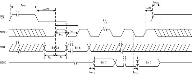 Figure 2. Serial Interface Read Timing Diagram
6.12 Typical Characteristics
6.12.1 Typical Characteristics: DAC
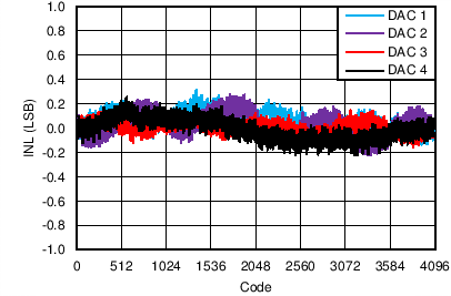
| DAC range = 0 to 5 V, AVDD = 5.5 V |
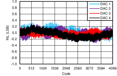
| DAC range = –5 to 0 V, AVSS = –5.5 V |
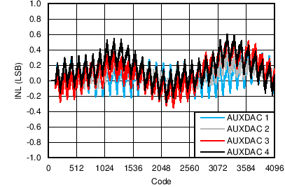
| DAC range = 0 to 5 V, AVCC = 5.5 V |
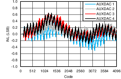
| DAC range = 2.5 to 7.5 V, AVCC = 12 V |
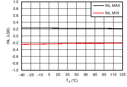
| DAC range = 0 to 5 V, AVDD = 5.5 V |
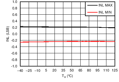
| DAC range = –5 to 0 V, AVSS = –5.5 V |
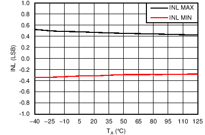
| DAC range = 0 to 5 V, AVCC = 5.5 V |
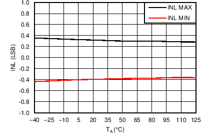
| DAC range = 2.5 to 7.5 V, AVCC = 12 V |
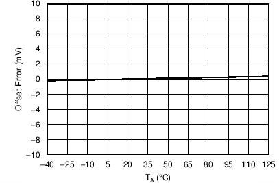
| DAC range = 0 to 5 V |
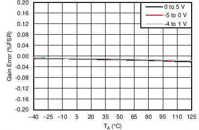
| AVDD = 5.5 V, AVSS = –5.5 V |
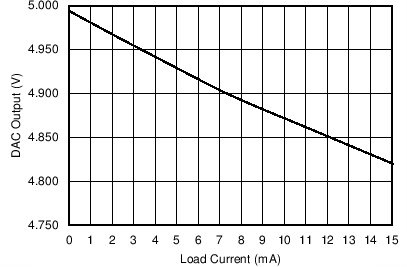
| DAC range = 0 to 5 V, Code 0xFFF |
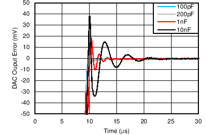
| Code 0x000 to 0xFFF to within 0.5% of final value |
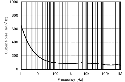
| Bipolar DAC, Code 0x800 |
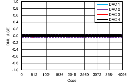
| DAC range = 0 to 5 V, AVDD = 5.5 V |
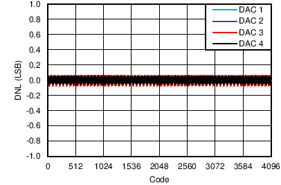
| DAC range = –5 to 0 V, AVSS = –5.5 V |
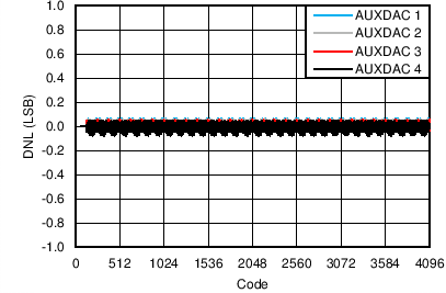
| DAC range = 0 to 5 V, AVCC = 5.5 V |
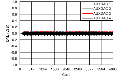
| DAC range = 2.5 to 7.5 V, AVCC = 12 V |
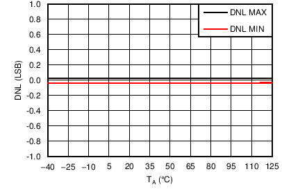
| DAC range = 0 to 5 V, AVDD = 5.5 V |
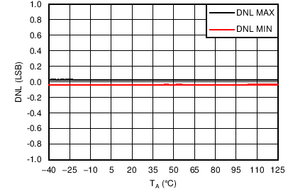
| DAC range = –5 to 0 V, AVSS = –5.5 V |
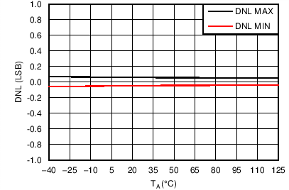
| DAC range = 0 to 5 V, AVCC = 5.5 V |
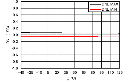
| DAC range = 2.5 to 7.5 V, AVCC = 12 V |
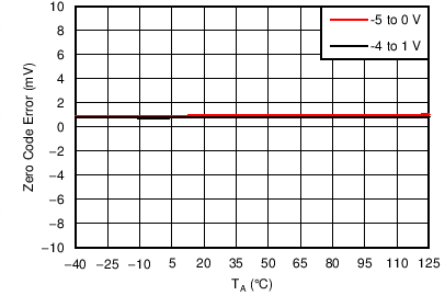
| AVSS = –5.5 V |
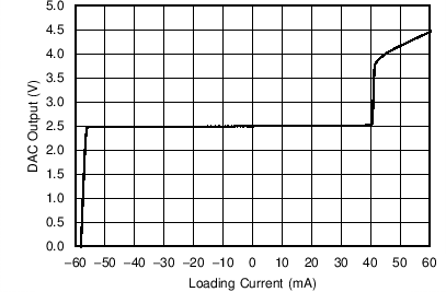
| DAC range = 0 to 5 V, Code 0x800 |
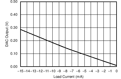
| DAC range = 0 to 5 V, Code 0x000, AVSS = 0 V |
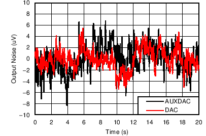
| Code 0x800 |
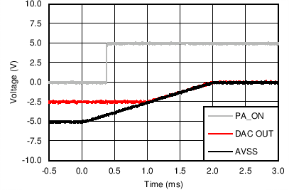
| DAC range: –5 to 0 V, Code 0x800 |
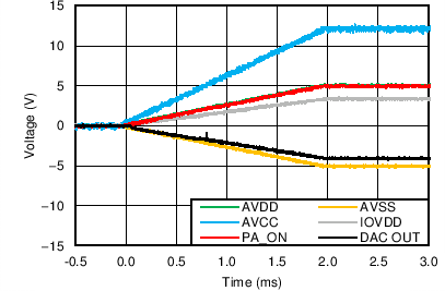
| DAC range: –4 to 1 V, VCLAMP[1:2] = 4/3 V |
6.12.2 Typical Characteristics: ADC
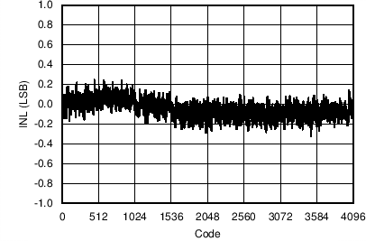
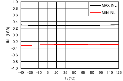
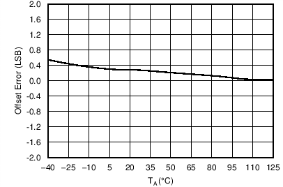
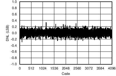
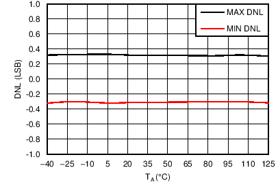
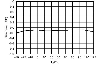
6.12.3 Typical Characteristics: Current Sense
| VCM = 28 V, VSENSE = 0 V, CS-FILTER[2:0] = 100 |
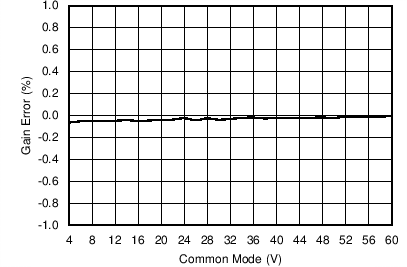
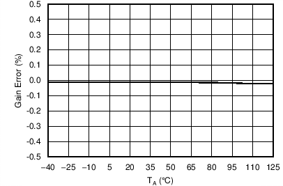
| VCM = 28 V |
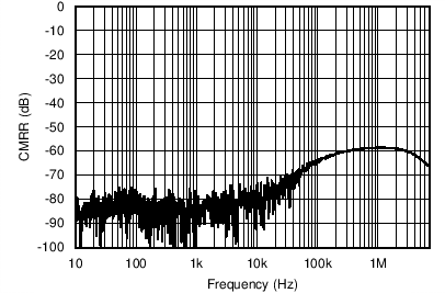
| CS-FILTER[2:0] = 100 |
6.12.4 Typical Characteristics: Temperature Sensor
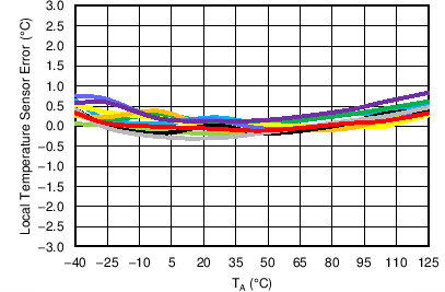
| 10 units |
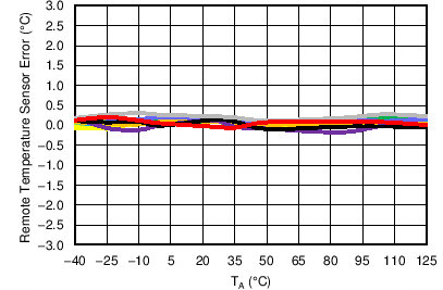
| 10 units, T(DIODE) = 25°C, RT-SET[2:0] = 011 |
6.12.5 Typical Characteristics: Reference
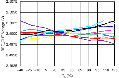
| 10 units |
