ZHCSSA7 october 2020 BQ25302
PRODUCTION DATA
- 1
- 1 特性
- 2 应用
- 3 说明
- 4 Revision History
- 5 说明(续)
- 6 Pin Configuration and Functions
- 7 Specifications
-
8 Detailed Description
- 8.1 Overview
- 8.2 Functional Block Diagram
- 8.3 Feature Description
- 8.4 Device Functional Modes
- 9 Application and Implementation
- 10Power Supply Recommendations
- 11Layout
- 12器件和文档支持
- 13Mechanical, Packaging, and Orderable Information
9.2.3 Typical Application with MCU Programmable Charge Current
In some application cases, the
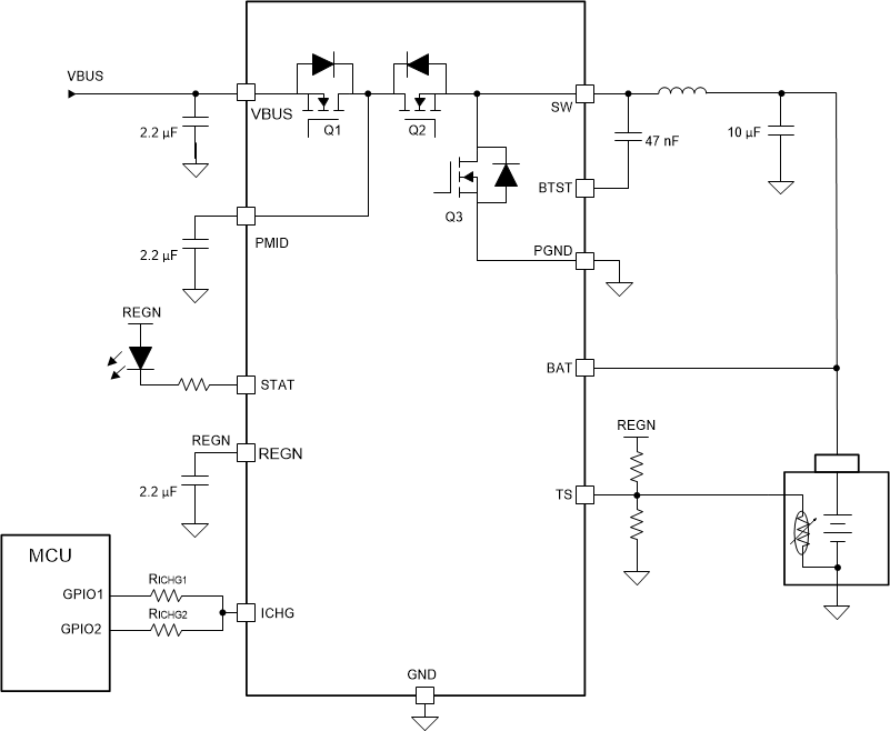
charge current needs to be controlled by a MCU. In those cases, the GPIOs of the MCU can
be used for on/off control of the charge current setting resistors RICHG1 and
RICHG2 as shown in Figure 9-7. With GPIO1 and GPIO2 on/off control, three levels of charge current
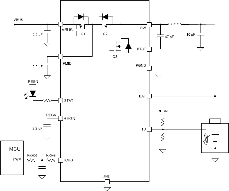
can be programmed. If the charge current needs to be controlled smoothly in a wide
range, a PWM output of the MCU can be used to generate an average DC voltage output to
program the charge current as shown in the Figure 9-7. The charge current can be calculated as: (1V - VPWM) / (RICHG1
+ RICHG2). VPWM is the averaged DC voltage of the PWM output and
it must be lower than 1 V. The regulated voltage at the ICHG pin is 1 V.
 Figure 9-7 Typical Application with MCU
Programmed Charge Current
  Figure 9-8 Typical Application with MCU Programmed Charge Current