ZHCSLX8B October 2020 – July 2024 BQ25618E , BQ25619E
PRODUCTION DATA
- 1
- 1 特性
- 2 应用
- 3 说明
- 4 说明(续)
- 5 器件比较表
- 6 引脚配置和功能
- 7 规格
- 8 详细说明
- 9 应用和实施
- 10电源相关建议
- 11布局
- 12器件和文档支持
- 13修订历史记录
- 14机械、封装和可订购信息
6 引脚配置和功能

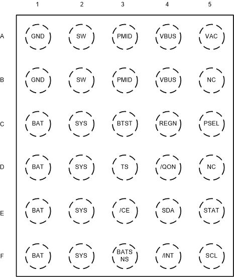
图 6-1 BQ25618E YFF 封装30 引脚 WCSP顶视图
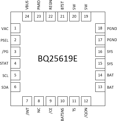
 图 6-2 BQ25619E RTW 封装24 引脚 WQFN顶视图
表 6-1 引脚功能
| 引脚 | 类型(1) | 说明 | ||
|---|---|---|---|---|
| 名称 | BQ25618E 编号 | BQ25619E 编号 | ||
| BAT | C1、D1、E1、F1 | 13、14 | P | 指向电池包正极端子的电池连接。内部电流检测电阻器连接在 SYS 和 BAT 之间。将 10µF 电容器连接到紧靠 BAT 引脚的位置。 |
| BATSNS | F3 | 10 | AIO | 用于充电电压调节的电池电压检测引脚。为了更大限度地减小充电期间的寄生引线电阻,BATSNS 引脚应连接到尽可能靠近电池包正极端子的位置。 |
| BTST | C3 | 21 | P | PWM 高侧驱动器正电源。在内部,BTST 连接到自举二极管的阴极。在 SW 和 BTST 之间连接一个 0.047μF 自举电容器。 |
| CE | E3 | 9 | DI | 充电使能引脚。当该引脚被驱动为低电平时,电池充电启用。 |
| GND | A1、B1 | 17、18 | P | 接地 |
| INT | F4 | 7 | DO | 开漏中断输出。通过 10kΩ 电阻器将 INT 连接到逻辑轨。INT 引脚向主机发送一个低电平有效的 256μs 脉冲,以报告充电器器件状态和故障。 |
| NC | B5、D5 | 8 | — | 未连接。保持该引脚悬空。 |
| PMID | A3、B3 | 23 | DO | 连接至反向阻断 MOSFET (RBFET) 的漏极和 HSFET 的漏极。考虑总输入电容,在 VBUS 和 GND 之间放置 1μF 电容,其余电容置于 PMID 和 GND 之间(典型值为 2x4.7μF + 1nF)。 |
| PG | 不适用 | 3 | DO | 开漏低电平有效电源正常指示器。通过 10kΩ 电阻器连接到上拉电源轨。如果输入电压介于 UVLO 和 ACOV 之间,高于睡眠模式阈值且电流限制高于 30mA,则低电平表示输入源正常。PG 仅适用于 BQ25619E,不适用于 BQ25618E。 |
| PSEL | C5 | 2 | DI | 电源选择输入。高电平表示输入电流限制为 500mA。低电平表示输入电流限制为 2.4A。器件进入主机模式后,主机可以将不同的输入电流限制编程到 IINDPM 寄存器。 |
| QON | D4 | 12 | DI | BATFET 使能/复位控制输入。当 BATFET 处于运输模式时,逻辑低电平持续 tSHIPMODE 时间将导通 BATFET 以退出运输模式。当 BATFET 不处于运输模式时,逻辑低电平持续 tQON_RST 时间(最短 8s)将通过使 BATFET 关断 tBATFET_RST 时间(最短 250ms)来复位 SYS(系统电源),然后重新启用 BATFET 以提供完全系统电源复位。主机通过 I2C 位 BATFET_RST_WVBUS 在 VBUS 拔出或未拔出的情况下选择 BATFET 复位功能。该引脚通过 200kΩ 电阻器上拉至 VBAT,以便在运输模式下保持默认的逻辑高电平。它有一个 6.5V 的内部钳位电压。 |
| REGN | C4 | 22 | P | PWM 低侧驱动器正电源输出。在内部,REGN 连接到自举二极管的阳极。在 REGN 到模拟 GND 之间连接一个 4.7μF(额定电压为 10V)的陶瓷电容器。电容器应靠近 IC 放置。 |
| SCL | F5 | 5 | DI | I2C 接口时钟。通过 10kΩ 电阻器将 SCL 连接到逻辑轨。 |
| SDA | E4 | 6 | DIO | I2C 接口数据。通过 10kΩ 电阻器将 SDA 连接到逻辑轨。 |
| STAT | E5 | 4 | DO | 开漏中断输出。通过 10kΩ 电阻器将 STAT 引脚连接到逻辑轨。STAT 引脚指示充电器状态。 正在进行充电:低电平 充电完成或充电器处于睡眠模式:高电平 充电暂停(故障响应):以 1Hz 的频率闪烁 |
| SW | A2、B2 | 19、20 | P | 连接到输出电感器的开关节点。在内部,SW 连接至 N 沟道 HSFET 的源极和 N 沟道 LSFET 的漏极。在 SW 和 BTST 之间连接一个 0.047μF 自举电容器。 |
| SYS | C2、D2、E2、F2 | 15、16 | P | 转换器输出连接点。内部电流检测电阻器连接在 SYS 和 BAT 之间。将 10µF(最小值)连接到紧靠 SYS 引脚的位置。 |
| TS | D3 | 11 | AI | 电池温度鉴定电压输入。连接一个负温度系数热敏电阻 (NTC)。使用从 REGN 到 TS 再到 GND 的电阻分压器对温度窗口进行编程。当 TS 引脚电压超出范围时,充电暂停。不使用 TS 引脚时,在 REGN 和 TS 之间连接一个 10kΩ 电阻器,并且在 TS 和 GND 之间连接一个 10kΩ 电阻器,或者将 TS_IGNORE 设置为高电平以忽略 TS 引脚。建议使用 103AT-2 热敏电阻。 |
| VAC | A5 | 1 | AI | 输入电压检测。该引脚必须连接至 VBUS。 |
| VBUS | A4、B4 | 24 | P | 充电器输入电压。内部 N 沟道反向阻断 MOSFET (RBFET) 连接在 VBUS 和 PMID 之间,同时 VBUS 位于源极。在 VBUS 和 GND 之间放置一个 1μF 陶瓷电容器,使之尽可能靠近 IC。 |
| 散热焊盘 | 不适用 | — | P | 器件的接地基准,也是用于传导器件热量的散热焊盘。此连接有两个用途。第一个用途是为器件提供电气接地连接。第二个用途是提供一条从器件芯片到 PCB 的低热阻抗路径。该散热焊盘应该在外部连接至接地层。 |
(1) AI = 模拟输入,AO = 模拟输出,AIO = 模拟输入/输出,DI = 数字输入,DO = 数字输出,DIO = 数字输入/输出,P = 电源