ZHCSGI9 August 2017
PRODUCTION DATA.
- 1 特性
- 2 应用
- 3 说明
- 4 修订历史记录
- 5 Pin Configuration and Functions
-
6 Specifications
- 6.1 Absolute Maximum Ratings
- 6.2 ESD Ratings
- 6.3 Recommended Operating Conditions
- 6.4 Thermal Information
- 6.5 Supply Current
- 6.6 Digital Input and Output DC Characteristics
- 6.7 LDO Regulator, Wake-up, and Auto-Shutdown DC Characteristics
- 6.8 LDO Regulator, Wake-up, and Auto-Shutdown AC Characteristics
- 6.9 ADC (Temperature and Cell Measurement) Characteristics
- 6.10 Integrating ADC (Coulomb Counter) Characteristics
- 6.11 I2C-Compatible Interface Communication Timing
- 6.12 SHUTDOWN and WAKE-UP Timing
- 6.13 Typical Characteristics
-
7 Detailed Description
- 7.1 Overview
- 7.2 Functional Block Diagram
- 7.3
Feature Description
- 7.3.1 Device Configuration
- 7.3.2 ALERT Interrupt and SHUTDOWN Wake-up
- 7.3.3 Voltage Measurement and Calibration
- 7.3.4 Temperature Measurement
- 7.3.5 Charging and Termination
- 7.3.6 Accumulated Charge Measurement
- 7.3.7 Gas Gauging
- 7.3.8 Battery Condition Warnings
- 7.3.9 Configuration Update
- 7.3.10 End-Of-Service Determination
- 7.3.11 Battery Level Threshold
- 7.3.12 Communications
- 7.3.13 Additional Data Memory Parameter Descriptions
- 7.4 Device Functional Modes
- 8 Application and Implementation
- 9 Power Supply Recommendation
- 10Layout
- 11器件和文档支持
- 12机械、封装和可订购信息
8 Application and Implementation
NOTE
Information in the following application section is not part of the TI component specification, and TI does not warrant its accuracy or completeness. TI’s customers are responsible for determining suitability of components for their purposes. Customers should validate and test their design implementation to confirm system functionality.
8.1 Application Information
The bq34210-Q1 fuel gauge is a microcontroller peripheral that provides system-side fuel gauging for 1-series cell batteries of a variety of chemistries. Battery fuel gauging with the fuel gauge requires connections only to PACK+ and PACK– for a removable battery pack or embedded battery circuit. To allow for optimal performance in the end application, special considerations must be taken to ensure minimization of measurement error through proper printed circuit board (PCB) board layout. Such requirements are detailed in Design Requirements.
8.1.1 Getting Started
To help configure and evaluate a bq34210-Q1 solution, Texas Instruments provides many supporting tools on the TI.com website, including the following:
- Battery Management Studio (bqStudio)
- Gauge Parameter Calculator for CEDV Gauges (GAUGEPARCAL)
- bqProduction to assist with the manufacturing process
These tools work with a TI EVM and with a self-designed solution. The bq34210-Q1 Technical Reference Manual (SLUUBE8) provides details on programming the gauge.
8.2 Typical Applications
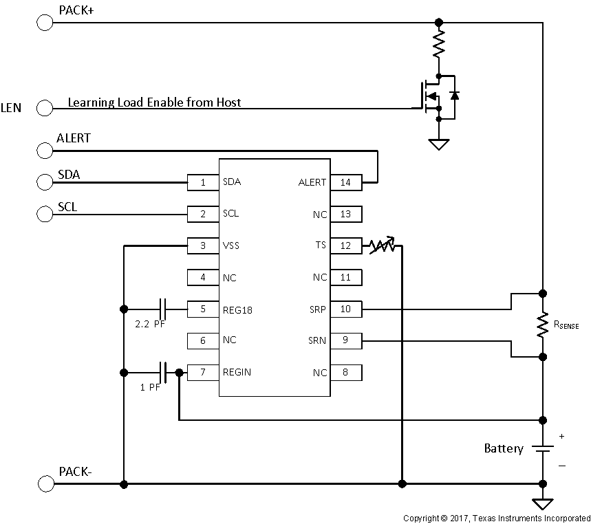
 Figure 5. Typical Application
8.2.1 Design Requirements
This design, for example, is for an automotive eCall solution. Calculate the required battery capacity by taking into account the required talk and standby time while in battery backup. Assume 10 minutes for a call followed by a 60-minute idle time (while pinging still occurs), and finally an additional 10-minute call. Understand the typical aging characteristics of the battery to know when the remaining capacity still fulfills the required capacity calculated previously. If the calculations show the requirement for a 1-Ah battery, a reasonable capacity battery to use would be 20% larger, or 1.2 mAh.
8.2.2 Detailed Design Procedure
8.2.2.1 REGIN Voltage Sense Input
A ceramic capacitor at the input to the REGIN pin is used to bypass AC voltage ripple to ground, greatly reducing its influence on battery voltage measurements.
8.2.2.2 Integrated LDO Capacitor
The fuel gauge has an integrated LDO with an output on the REG18 pin of approximately 1.8 V. A capacitor of at least a 2.2-μF value should be connected between the REG18 pin and VSS. The capacitor must be placed close to the fuel gauge and have short traces to both the REG18 pin and VSS. This regulator must not be used to provide power for other devices in the system.
8.2.2.3 Sense Resistor Selection
Any variation encountered in the resistance present between the SRP and SRN pins of the fuel gauge will affect the resulting differential voltage and derived current it senses. As such, it is recommended to select a sense resistor with minimal tolerance and temperature coefficient of resistance (TCR) characteristics. The standard recommendation based on best compromise between performance and price is a 1% tolerance, 50-ppm drift sense resistor with a 1-W power rating. The power rating must be consistent with the maximum current and sense resistor value. The bq34210-Q1 device supports sense resistors from 5 mΩ to 20 mΩ.
8.2.3 External Thermistor Support
The fuel gauge temperature sensing circuitry is designed to work with a negative temperature coefficient-type (NTC) thermistor with a characteristic 10-kΩ resistance at room temperature (25°C). The default curve-fitting coefficients configured in the fuel gauge specifically assume a Semitec 103AT type thermistor profile and so that is the default recommendation for thermistor selection purposes. Moving to a separate thermistor resistance profile (for example, JT-2 or others) requires an update to the default thermistor coefficients, which can be modified in RAM to ensure highest accuracy temperature measurement performance. For more details, see the Temperature Measurement section of the bq34210-Q1 TRM (SLUUBE8).
8.2.4 Learning Load Enable (LEN) from Host
The learning load helps to determine the status of the battery (EOS). The host must control the load during the learning phase and put the bq34210-Q1 gauge into the learning phase. The resistance is set by selecting the learning current. With 220 mA and the charge voltage of 4.2 V, use Ohm's law to calculate the resistance (19.09 Ω).
8.2.5 I2C
If the external pullup resistors on the SCL and SDA lines will be disconnected from the host during low-power operation, it is recommended to use external 1-MΩ pulldown resistors to VSS to avoid floating inputs to the I2C engine.
The value of the SCL and SDA pullup resistors should take into consideration the pullup voltage and the bus capacitance along with the communication speed. Many communication errors are a result of improper sizing of the resistors. Rounding of the clock and data signals indicated improper RC configurations. The maximum pullup resistance (RPUmax) can be estimated by this equation:
RPUmax = tr / (0.4873 × CBUS)
Where tr is the rise time and CBUS is the total bus capacitance.
Assuming a bus capacitance of 10 pF, Table 1 shows some recommended values.
Table 1. Recommended Values for SCL and SDA Pullup Resistors
| VPU | 1.8 V | 3.3 V | ||
|---|---|---|---|---|
| RPU | Range | Typical | Range | Typical |
| 400 Ω ≤ RPU ≤ 37.6 kΩ | 10 kΩ | 900 Ω ≤ RPU ≤ 29.2 kΩ | 5.1 kΩ | |
8.2.6 Temperature Sense
The TS pin is used to measure the system temperature.
If the battery pack thermistor is not connected to the TS pin, the TS pin should be pulled down to VSS with a 10-kΩ resistor. The TS pin must not be shorted directly any other pin.
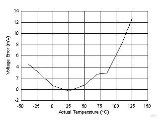
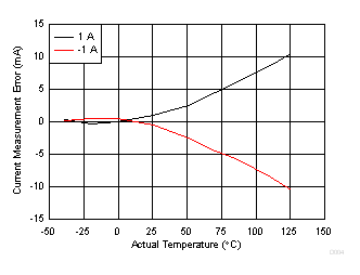
8.2.7 Application Curves

| REGIN = 3.7 V | ||
