ZHCS327D July 2011 – October 2016
PRODUCTION DATA.
- 1 特性
- 2 应用
- 3 说明
- 4 修订历史记录
- 5 说明 (续)
- 6 Pin Configuration and Functions
-
7 Specifications
- 7.1 Absolute Maximum Ratings
- 7.2 ESD Ratings
- 7.3 Recommended Operating Conditions
- 7.4 Thermal Information
- 7.5 Electrical Characteristics: Supply Current
- 7.6 Internal Power Control (Startup and Shutdown)
- 7.7 3.3-V Voltage Regulator
- 7.8 Voltage Reference
- 7.9 Cell Voltage Amplifier
- 7.10 Current Sense Amplifier
- 7.11 Overcurrent Comparator
- 7.12 Internal Temperature Measurement
- 7.13 Cell Balancing and Open Cell Detection
- 7.14 I2C Compatible Interface
- 7.15 Typical Characteristics
-
8 Detailed Description
- 8.1 Overview
- 8.2 Functional Block Diagram
- 8.3 Feature Description
- 8.4 Device Functional Modes
- 8.5 Programming
- 8.6 Register Maps
- 9 Application and Implementation
- 10Power Supply Recommendations
- 11Layout
- 12器件和文档支持
- 13机械、封装和可订购信息
封装选项
机械数据 (封装 | 引脚)
散热焊盘机械数据 (封装 | 引脚)
- RGE|24
订购信息
1 特性
- 用于主机电芯测量的模拟接口
- 电芯输入多路开关、电平转换器和缩放器
- 经过校准的 1.5V/3.0V 低漂移基准电压,可实现精确模数转换
- 用于主机电流测量的模拟接口
- 可变增益电流感测放大器,能够与 1mΩ 感测电阻搭配运行
- 用于主机温度测量的可切换热敏电阻偏置输出
- 阈值可动态调节的过流比较器
- 向主机报告潜在的过流故障
- 在连接负载后唤醒主机
- 集成电芯均衡场效应晶体管 (FET)
- 单独主机控制
- 每个电芯的均衡电流为 50mA
- 支持电芯感测线路开路检测
- 集成有用于为微控制器或 LED 供电的 3.3V 稳压器
- 用于主机通信的 I2C 接口
- 可选数据包循环冗余校验 (CRC),用于确保通信的稳健性
- 电源电压范围:4.2V 至 26.4V
- 低功耗
- 正常模式下的电流典型值为 40µA
- 休眠模式下的电流最大值为 1.5µA
- 采用 20 引脚散热薄型小外形尺寸 (HTSSOP) 或 24 引脚超薄四方扁平无引线 (VQFN) 封装
2 应用
- 锂离子电池组主保护
- 无绳电动工具
- 轻型电动车辆(电动自行车和电动踏板车等)
- 不间断电源 (UPS) 系统
- 医疗设备
- 便携式测试设备
3 说明
Bq76925 是一款由主机控制的模拟前端 (AFE),它是一套完备电池组监视、均衡和保护系统的组成部分,这套系统适用于 3、4、5 或 6 节串联锂离子和锂聚合物电池。bq76925 器件通过一个主机控制器轻松监视各电芯电压、电池组电流及温度。主机可利用这些信息确定不安全或故障运行情况,例如过压、欠压、过热、过流、电芯电量失衡、充电状态和健康状况。
电芯输入电压经电平转换、多路选择、缩放后输出,以供主机 ADC 测量。一个专用引脚提供了经校准的低漂移基准电压,从而实现精确测量。
器件信息(1)
| 器件型号 | 封装 | 封装尺寸(标称值) |
|---|---|---|
| bq76925 | TSSOP (20) | 4.00mm x 4.00mm |
| bq76925 | VQFN (24) | 6.50mm x 4.40mm |
- 要了解所有可用封装,请见数据表末尾的可订购米6体育平台手机版_好二三四附录。
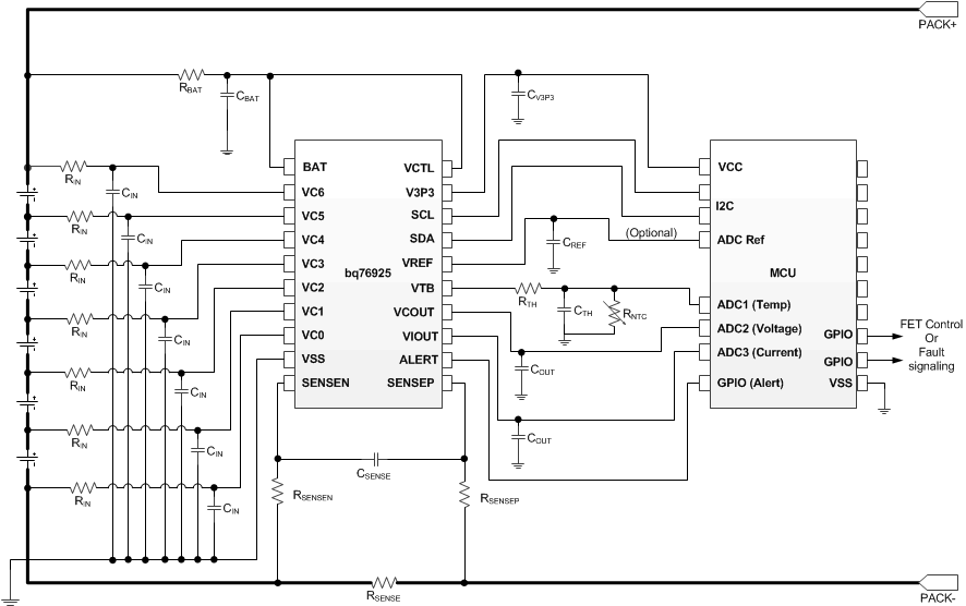
简化电路原理图
