ZHCS267A May 2011 – December 2016
PRODUCTION DATA.
- 1 特性
- 2 应用
- 3 说明
- 4 修订历史记录
- 5 Pin Configuration and Functions
- 6 Specifications
-
7 Detailed Description
- 7.1 Overview
- 7.2 Functional Block Diagram
- 7.3
Feature Description
- 7.3.1
Analog-to-Digital Conversion (ADC)
- 7.3.1.1 General Features
- 7.3.1.2 3-to-6 Series Cell Configuration
- 7.3.1.3 Cell Voltage Measurements
- 7.3.1.4 GPAI or VBAT Measurements
- 7.3.1.5 Temperature Measurement
- 7.3.1.6 ADC Band-Gap Voltage Reference
- 7.3.1.7 Conversion Control
- 7.3.1.8 Secondary Protection
- 7.3.1.9 Cell Overvoltage Fault Detection (COV)
- 7.3.1.10 Cell Undervoltage Fault Detection (CUV)
- 7.3.1.11 Overtemperature Detection
- 7.3.1.12 Fault and Alert Behavior
- 7.3.1.13 Secondary Protector Built-In Self-Test Features
- 7.3.2 Cell Balancing
- 7.3.3 Other Features and Functions
- 7.3.4 Communications
- 7.3.1
Analog-to-Digital Conversion (ADC)
- 7.4 Device Functional Modes
- 7.5 Programming
- 7.6
Register Maps
- 7.6.1 I/O Register Details
- 7.6.2 Register Types
- 7.6.3
Register Details
- 7.6.3.1 DEVICE_STATUS Register (0x00)
- 7.6.3.2 GPAI (0x01, 0x02) Register
- 7.6.3.3 VCELLn Register (0x03…0x0e)
- 7.6.3.4 TEMPERATURE1 Register (0x0f, 0x10)
- 7.6.3.5 TEMPERATURE2 Register (0x11, 0x12)
- 7.6.3.6 ALERT_STATUS Register (0x20)
- 7.6.3.7 FAULT_STATUS Register (0x21)
- 7.6.3.8 COV_FAULT Register (0x22)
- 7.6.3.9 CUV_FAULT Register (0x23)
- 7.6.3.10 PARITY_H Register (0x24) [PRESULT_A (R/O)]
- 7.6.3.11 PARITY_H Register (0x25) [PRESULT_B (R/O)]
- 7.6.3.12 ADC_CONTROL Register (0x30)
- 7.6.3.13 IO_CONTROL Register (0x31)
- 7.6.3.14 CB_CTRL Register (0x32)
- 7.6.3.15 CB_TIME Register (0x33)
- 7.6.3.16 ADC_CONVERT Register (0x34)
- 7.6.3.17 SHDW_CTRL Register (0x3a)
- 7.6.3.18 ADDRESS_CONTROL Register (0x3b)
- 7.6.3.19 RESET Register (0x3c)
- 7.6.3.20 TEST_SELECT Register (0x3d)
- 7.6.3.21 E_EN Register (0x3f)
- 7.6.3.22 FUNCTION_CONFIG Register (0x40)
- 7.6.3.23 IO_CONFIG Register (0x41)
- 7.6.3.24 CONFIG_COV Register (0x42)
- 7.6.3.25 CONFIG_COVT Register (0x43)
- 7.6.3.26 CONFIG_UV Register (0x44)
- 7.6.3.27 CONFIG_CUVT Register (0x45)
- 7.6.3.28 CONFIG_OT Register (0x46)
- 7.6.3.29 CONFIG_OTT Register (0x47)
- 7.6.3.30 USERx Register (0x48-0x4b) (USER1-4)
- 8 Application and Implementation
- 9 Power Supply Recommendations
- 10Layout
- 11器件和文档支持
- 12机械、封装和可订购信息
6 Specifications
6.1 Absolute Maximum Ratings
over operating free-air temperature range (unless otherwise noted) (1)| MIN | MAX | UNIT | |||
|---|---|---|---|---|---|
| VMAX | Supply voltage | BAT1, BAT2(2) | –0.3 | 36 | V |
| VIN | Input voltage | VC1, VC2, VC3, VC4, VC5, VC6 | –0.3 | 36 | V |
| VC0 | –0.3 | 2 | |||
| TS1+, TS1–, TS2+, TS2– | –0.3 | 6 | |||
| GPAI | –0.3 | 6 | |||
| GPIO | –0.3 | VREG50 + 0.3 | |||
| DRDY_N, SDO_N, FAULT_N, ALERT_N | VBAT – 1 | VBAT + 2 | |||
| CONV_H, SDI_H, SCLK_H, CS_H | –0.3 | 6 | |||
| CONV_S, SDI_S, SCLK_S, CS_S | –2 | 1 | |||
| VO | Output voltage | CONV_N, SDI_N, SCLK_N, CS_N | –0.3 | 36 | V |
| SDO_H, FAULT_H, ALERT_H, DRDY_H | –0.3 | 6 | |||
| DRDY_S, SDO_S, FAULT_S, ALERT_S | –0.3 | 5 | |||
| GPIO | –0.3 | VREG50 + 0.3 | |||
| CB1…CB6 (CBREF = 0x00) | –0.3 | 36 | |||
| REG50, AUX | –0.3 | 6 | |||
| TJ | Junction temperature | 150 | °C | ||
| Tstg | Storage temperature | –65 | 150 | °C | |
(1) Stresses beyond those listed under Absolute Maximum Ratings may cause permanent damage to the device. These are stress ratings only, which do not imply functional operation of the device at these or any other conditions beyond those indicated under Recommended Operating Conditions. Exposure to absolute-maximum-rated conditions for extended periods may affect device reliability.
(2) All voltages are with respect to VSS of this device, except where otherwise noted.
6.2 ESD Ratings
| VALUE | UNIT | ||||
|---|---|---|---|---|---|
| V(ESD) | Electrostatic discharge | Human-body model (HBM), per AEC Q100-002(1) | ±2000 | V | |
| Charged-device model (CDM), per AEC Q100-011 | All pins | ±500 | |||
| Corner pins (1,16, 33, and 48) | ±750 | ||||
(1) AEC Q100-002 indicates that HBM stressing shall be in accordance with the ANSI/ESDA/JEDEC JS-001 specification.
6.3 Recommended Operating Conditions
Typical values stated where TA = 25°C and VBAT = 22 V, Min/Max values stated where TA = –40°C to +105°C andVBAT = 7.2 V to 27 V (unless otherwise noted)
| MIN | NOM | MAX | UNIT | |||
|---|---|---|---|---|---|---|
| VBAT | Supply voltage | BAT | 7.2 | 27 | V | |
| VI | Input voltage | VCn–VC(n – 1)(1) | 1 | 4.5 | V | |
| GPAI | 0 | 2.5 | ||||
| GPIO | 0 | VREG50 | ||||
| CBn(1) | VC(n – 1) | VCn | ||||
| TS1+, TS1–, TS2+, TS2– | 0 | VREG50/2 | ||||
| Non-top IC in stack: DRDY_N, SDO_N, FAULT_N, ALERT_N | BAT + 1 | |||||
| Top IC in stack: DRDY_N, SDO_N, FAULT_N, ALERT_N | BAT | |||||
| Non-bottom IC in stack: CONV_S, SDI_S, SCLK_S, CS_S | –1 | |||||
| Bottom IC in stack: CONV_S, SDI_S, SCLK_S, CS_S | VSS | |||||
| VO | Output voltage | Non-bottom IC in stack : CONV_N, SDI_N, SCLK_N, CS_N | 1 | V | ||
| Bottom IC in stack: CONV_N, SDI_N, SCLK_N, CS_N | VSS | |||||
| Non-top IC in stack: DRDY_S, SDO_S, FAULT_S, ALERT_S | BAT – 1 | |||||
| Top IC in stack: DRDY_S, SDO_S, FAULT_S, ALERT_S | BAT | |||||
| CREG50 | External capacitor | REG50 pin | 2.2 | µF | ||
| CVREF | External capacitor | VREF pin | 9.2 | 10 | 15 | µF |
| CLDO | External capacitor | LDOx pin | 2.2 | 3.3 | µF | |
| TOPR | Operating temperature(2) | –40 | 105 | °C | ||
(1) n = 1 to 6
(2) Device specifications stated within this range.
6.4 Thermal Information
| THERMAL METRIC(1) | bq76PL536A-Q1 | UNIT | |
|---|---|---|---|
| PAP (HTQFP) | |||
| 64 PINS | |||
| RθJA | Junction-to-ambient thermal resistance | 24.6 | °C/W |
| RθJC(top) | Junction-to-case (top) thermal resistance | 10 | °C/W |
| RθJB | Junction-to-board thermal resistance | 8.1 | °C/W |
| ψJT | Junction-to-top characterization parameter | 0.3 | °C/W |
| ψJB | Junction-to-board characterization parameter | 8 | °C/W |
| RθJC(bot) | Junction-to-case (bottom) thermal resistance | 0.4 | °C/W |
(1) For more information about traditional and new thermal metrics, see the Semiconductor and IC Package Thermal Metrics application report.
6.5 Electrical Characteristics
Typical values stated where TA = 25°C and VBAT = 22 V, Min/Max values stated where TA = –40°C to +105°C andVBAT = 7.2 V to 27 V (unless otherwise noted)
| PARAMETER | TEST CONDITIONS | MIN | TYP | MAX | UNIT | |
|---|---|---|---|---|---|---|
| SUPPLY CURRENT | ||||||
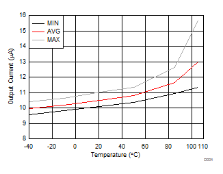
| ICCSLEEP | Supply current | No load at REG50, SCLK_N, SDI_N, SDO_N, FAULT_N, CONV_N, DRDY_S, ALERT_N, TSx, AUX, or CBx; CB_CTRL = 0; CBT_CONTROL = 0; CONV_H = 0 (not converting), IO_CONTROL[SLEEP] = 1 |
12 | 22 | µA | |
| ICCPROTECT | Supply current | No load at REG50, SCLK_N, SDI_N, SDO_N, FAULT_N, CONV_N, DRDY_S, ALERT_N, TSx, AUX, or CBx; CB_CTRL = 0; CBT_CONTROL = 0; CONV_H = 0 (not converting), IO_CONTROL[SLEEP] = 0 |
45 | 60 | µA | |
| ICCBALANCE | Supply current | No load at REG50, SCLK_N, SDI_N, SDO_N, FAULT_N, CONV_N, DRDY_S, ALERT_N, TSx, or AUX; No DC load at CBx; CB_CTRL ≠ 0; CBT_CONTROL ≠ 0; CONV_H = 0 (not converting) , IO_CONTROL[SLEEP] = 0 |
46 | 60 | µA | |
| ICCCONVERT | Supply current | No load at REG50, SCLK_N, SDI_N, SDO_N, FAULT_N, CONV_N, DRDY_S, ALERT_N, TSx or CBx; CONV_S = 1 (conversion active) , IO_CONTROL[SLEEP] = 0 | 10.5 | 15 | mA | |
| ICCTSD | Supply current | Thermal shutdown activated; ALERT_STATUS[TSD] = 1 | 1.6 | mA | ||
| REG50, INTEGRATED 5-V LDO | ||||||
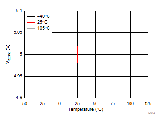
| VREG50 | Output voltage | IREG50OUT ≤ 0.5 mA, C = 2.2 µF to 22 µF | 4.9 | 5 | 5.1 | V |
| ΔVREG50LINE | Line regulation | 7.2 V ≤ BAT ≤ 27 V, IREG50OUT = 2 mA | 10 | 25 | mV | |
| ΔVREG50LOAD | Load regulation | 0.2 mA ≤ IREG50OUT ≤ 2 mA | 15 | mV | ||
| 0.2 mA ≤ IREG50OUT ≤ 5 mA | 25 | |||||
| IREG50MAX | Current limit | 12 | 25 | 35 | mA | |
| IAUXMAX | Maximum load | AUX pin | 5 | mA | ||
| RAUX | AUX output | I = 1 mA, max. capacitance = VREG50
Capacitor: CVAUX ≤ CVREG50 / 10 |
50 | Ω | ||
| LEVEL SHIFT INTERFACE | ||||||
| INTX1 | North 1 transmitter current | SCLK_N, CS_N, SDI_N, CONV_N | 1000 | 1350 | 1800 | µA |
| INTX0 | North 0 transmitter current | CS_N, CONV_N | 1 | µA | ||
| INTX0A | North 0 transmitter current | SCLK_N, SDI_N (BASE device CS_H = 1) | 1 | µA | ||
| INTX0B | North 0 transmitter current | SCLK_N, SDI_N (BASE device CS_H = 0) | 50 | 75 | 110 | µA |
| ISRX | South 1 receiver threshold | SCLK_S, CS_S, SDI_S, CONV_S | 430 | 550 | 680 | µA |
| ISRXH | South receiver hysteresis | SCLK_S, CS_S, SDI_S, CONV_S | 100 | 200 | µA | |
| ISTX1 | South 1 transmitter current | ALERT_N, FAULT_S, DRDY_S | 800 | 1100 | 1400 | µA |
| ISTX0 | South 0 transmitter current | ALERT_S, FAULT_S, DRDY_S | 1 | µA | ||
| ISTX0A | South 0 transmitter current | SDO_S (BASE device CS_H = 1) | 1 | µA | ||
| ISTX0B | South 0 transmitter current | SDO_S (BASE device CS_H = 0) | 1 | 4 | 7 | µA |
| INRX | North 1 receiver threshold | SDO_N, ALERT_N, FAULT_N, DRDY_N | 420 | 580 | 720 | µA |
| INRXH | North receiver hysteresis | SDO_N, ALERT_N, FAULT_N, DRDY_N | 50 | 100 | 200 | µA |
| CIN | Input capacitance | 15 | pF | |||
| HOST INTERFACE | ||||||
| VOH | Logic-level output voltage, high; SDO_H, FAULT_H, ALERT_H, DRDY | CL = 20 pF, IOH < 5 mA(1) | 4.5 | VLDOD | V | |
| VOL | Logic-level output voltage, low; SDO_H, FAULT_H, ALERT_H, DRDY | CL = 20 pF, IOL < 5 mA(1) | VSS | 0.5 | V | |
| VIH | Logic-level input voltage, high; SCLK_H, SDI_H, CS_H, CONV | 2 | V | |||
| VIL | Logic-level input voltage, low; SCLK_H, SDI_H, CS_H, CONV | 0.8 | V | |||
| CIN | Input Capacitance CONV_H(2)
Input Capacitance CS_H(3) Input Capacitance SCLK_H, SDI_H |
5 | pF | |||
| ILKG | IInput leakage current CONV_H(2)
Input leakage current CS_H(3) Input leakage current SCLK_H, SDI_H |
1 | µA | |||
| GENERAL PURPOSE INPUT/OUTPUt (GPIO) | ||||||
| VIH | Logic-level input voltage, high | Vin ≤ VREG50 | 2 | V | ||
| VIL | Logic-level input voltage, low | 0.8 | V | |||
| VOH | Output high-voltage pull-up voltage | Supplied by external approximately 100-kΩ resistor | VREG50 | V | ||
| VOL | Logic-level output voltage, low | IOL = 1 mA | 0.3 | V | ||
| CIN | Input capacitance(1) | 5 | pF | |||
| ILKG | Input leakage current | 1 | µA | |||
| CELL BALANCING CONTROL OUTPUT (CBx) | ||||||
| CBz | Output impedance | 1 V < VCELL < 5 V | 80 | 100 | 125 | kΩ |
| VRANGE | Output V | VCn-1 | VCn | V | ||
| ADC COMMON SPECIFICATIONS | ||||||
| tCONV_START | CONV high to conversion start(4) (5) | ADC_CONTROL[ADC_ON] = 1 | 5.4 | 6 | 6.6 | µs |
| ADC_CONTROL[ADC_ON] = 0 | 500 | µs | ||||
| tCONV | Conversion time per selected channel(6) | ADC_CONTROL[ADC_ON] = 1 | 5.4 | 6 | 6.6 | µs |
| ILKG | Input leakage current | Not converting, measured differentially | <10 | 100 | nA | |
| VCn (CELL) INPUTS(7) | ||||||
| VIN | Input voltage range(8) | VCn – VCn–1, where n = 1 to 6 | 0 | 6 | V | |
| VRES | Voltage resolution(9) | 14 bits | ~378 | µV | ||
| VACC | Voltage accuracy, total error, VIN = VCn to VCn–1 |
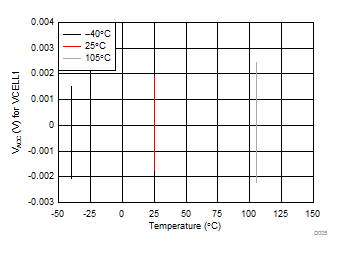
–10°C ≤ TA ≤ 50°C, 1.2 V < VIN < 4.5 V | –2.5 | ±1 | 2.5 | mV |
| –40°C ≤ TA ≤ 105°C, 1.2 V < VIN < 4.5 V | –5 | 5 | ||||
| RIN | Effective input resistance | Converting | 2 | MΩ | ||
| CIN | Input capacitance | Converting | 1 | pF | ||
| EN | Noise | VIN = 3 V | 250 | µVRMS | ||
| VBAT (VBRICK) MEASUREMENT(11) | ||||||
| VIN | Input voltage range, BATn to VSS | FUNCTION_CONFIG[] = 0101xx00b | 0 | 30 | V | |
| VRES | Voltage resolution(10) | 14 bits | ~1.831 | mV | ||
| VACC | Voltage accuracy | Total error 7.2 V ≤ VIN ≤ 27 V | –80 | –30 | 20 | mV |
| CIN | Input capacitance | Converting | 1 | pF | ||
| RIN | Effective input resistance | Converting | 50 | kΩ | ||
| EN | Noise | 1.5 | mVRMS | |||
| GPAI MEASUREMENT(12) | ||||||
| VIN | Input voltage range,(13) GPAI+ to GPAI– | 0 | 2.5 | V | ||
| VRES | Voltage resolution(14) | 14 bits | ~153 | µV | ||
| VACC | Voltage accuracy, VIN = GPAI+ – GPAI– | 0.25 V ≤ VIN ≤ 2.5 V | –7 | 7 | mV | |
| VIN = 1.25 V, TA = 25°C | ±2 | |||||
| CIN | Input capacitance | Converting | 40 | pF | ||
| RIN | Effective input resistance | Converting | 50 | kΩ | ||
| EN | Noise | 150 | µVRMS | |||
| TSn MEASUREMENT(15) | ||||||
| VIN | Input voltage range,(16) TSn+ TSn– | 0 | 2.5 | V | ||
| VRES | Voltage resolution(17) | 14 bits, REG50 = 5 V, (Resolution ≈ VREG50 / 215) |
≈153 | µV | ||
| VACC | Ratio accuracy, % of input(17) | 45 mV ≤ VIN < 250 mV | –3.5% | ±1% | +3.5% | |
| 250 mV ≤ VIN ≤ 2.4 V | –0.5% | ±0.2% | +0.5% | |||
| CIN | Input capacitance | Converting | 40 | pF | ||
| RIN | Effective input resistance | Converting | 50 | kΩ | ||
| EN | Noise | 150 | µVRMS | |||
| THERMAL SHUTDOWN | ||||||
| TSD | Shutdown threshold | VBAT = 22 V | 125 | 142 | 156 | °C |
| THYS | Recovery hysteresis | 8 | 25 | °C | ||
| UNDERVOLTAGE LOCKOUT (UVLO) and POWER-ON RESET (POR) | ||||||
| VUVLO | Negative-going threshold | 5 | 5.6 | V | ||
| VUVLO_HSY | Hysteresis | 250 | 375 | 500 | mV | |
| UVLODELAY | Delay to locked-out condition | V ≤ VUVLO MIN | 15 | μs | ||
| VPOR | Negative-going threshold | 4 | 5 | V | ||
| VPOR_HSY | Hysteresis | 250 | 500 | 750 | mV | |
| PORDELAY | Delay to disabled condition | V ≤ VPOR MIN | 15 | µs | ||
| tRST | Reset delay time | V ≥ VPOR + VPOR_HSY | 40 | 56 | 70 | ms |
| VDELTA_RISE | Voltage delta between trip points | VUVLO – VPOR (VBAT rising) | 0.25 | 0.4 | 0.7 | V |
| VDELTA_FALL | Voltage delta between trip points | VUVLO – VPOR (VBAT falling) | 0.4 | 0.52 | 0.7 | V |
| BATTERY PROTECTION THRESHOLDS | ||||||
| VOVR | OV detection threshold range(18) | VBAT = 12 V and 27 V | 2 | 5 | V | |
| ΔVOVS | OV detection threshold program step | VBAT = 12 V and 27 V | 50 | mV | ||
| VOVH | OV detection hysteresis | VBAT = 12 V and 27 V | 50 | mV | ||
| VOVA1 | OV detection threshold accuracy | 3.3 ≤ VOV_SET ≤ 4.5 | –50 | 0 | 50 | mV |
| VOVA2 | OV detection threshold accuracy | VOV_SET < 3.3 or VOV_SET > 4.5 | –70 | 0 | 70 | mV |
| VUVR | UV detection threshold range(18) | VBAT = 22 V | 700 | 3300 | mV | |
| ΔVUVS | UV detection threshold program step | VBAT = 22 V | 100 | mV | ||
| VUVH | UV detection hysteresis | VBAT = 22 V | 100 | mV | ||
| VUVA | UV detection threshold accuracy | –100 | 0 | 100 | mV | |
| VOTR | OT detection threshold range(19) | VREG50 = 5 V | 1 | 2 | V | |
| ΔVOTS | OT detection threshold program step(19) | See (20) | V | |||
| VOTA | OT detection threshold accuracy(19) | T = 40°C to 90°C | –0.015 | 0.01 | 0.05 | V |
| ΔVOTH | OT reset hysteresis(21) | T = 40°C to 90°C | 8% | 12% | 15% | |
| BATTERY PROTECTION DELAY TIMES | ||||||
| tOV | OV detection delay-time range | 0 | 3200 | ms | ||
| ΔtOV | OV detection delay-time step | COVT [µs] = 0 | 100 | µs | ||
| COVT [ms] = 1 | 100 | ms | ||||
| tUV | UV detection delay-time range | 0 | 3200 | ms | ||
| ΔtUV | UV detection delay-time step | CUVT[7] (µs) = 0 | 100 | µs | ||
| CUVT[7] (ms) = 1 | 100 | ms | ||||
| tOT | OT detection delay-time range | 0 | 2550 | ms | ||
| ΔtOT | OT detection delay-time step | 10 | ms | |||
| tacr | OV, UV, and OT detection delay-time accuracy(22) | CUVT, (COVT) ≥ 500 µs | –12% | 0% | 10% | |
| t(DETECT) | Protection comparator detection time | VOT or VOV or VUV threshold exceeded by 10 mV | 100 | µs | ||
| OTP EPROM PROGRAMMING CHARACTERISTICS | ||||||
| VPROG | Programming voltage | VBAT ≥ 22 V | 6.75 | 7 | 7.25 | V |
| tPROG | Programming time | 50 | ms | |||
| IPROG | Programming current | 10 | 20 | mA | ||
(1) Total simultaneous current drawn from all pins is limited by LDOD current to ≤ 10 mA.
(2) Pin has 250-nA internal sink to VSS.
(3) Pin has 100-kΩ internal pull-up resistor.
(4) If ADC_CONTROL[ADC_ON] = 0, add 500 µs to conversion time to allow ADC subsystem to stabilize. This is self-timed by the part.
(5) Additional 50 ms (POR) is required before first conversion after a) initial cell connection; or b) VBAT falls below VPOR.
(6) Plus tCONV_START, that is, if device is programmed for six channel conversions, total time is approximately 6 × 6 + 6 = 42 µs.
(7) FUNCTION_CONFIG[]=01xxxx00b for all test conditions (6-µs conversion time selected).
(8) 0 V may not lie within the range of measured values due to offset voltage limit and device calibration.
(9) See text for specific conversion formula.
(10) See text for specific conversion formula.
(11) FUNCTION_CONFIG[] = 01xxxx00b for all test conditions
(12) FUNCTION_CONFIG[] = 0101xx00b for all test conditions
(13) 0 V may not lie within the range of measured values due to offset voltage limit and device calibration.
(14) See text for specific conversion formula.
(15) FUNCTION_CONFIG[]=01xxxx00b for all Test Conditions
(16) 0 V may not lie within the range of measured values due to offset voltage limit and device calibration.
(17) See text for specific conversion formula.
(18) COV and CUV thresholds must be set such that COV – CUV ≥ 300 mV
(19) Using recommended components. Consult Table 2 in text for voltage levels used.
(20) See Table 2 for trip points.
(21) Hysteresis measured to trip point voltage.
(22) Under double or multiple fault conditions (of a single type), the second or greater fault may have its delay time shortened by up to the step time for the fault. For example, the second and subsequent COV faults occurring within the delay time period for the first fault may have their delay time shortened by up to 100 µs.
6.6 Timing Requirements: AC SPI Data Interface
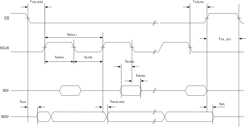
Typical values stated where TA = 25°C and VBAT = 22 V, Min/Max values stated where TA = –40°C to +105°C andVBAT = 7.2 V to 27 V (unless otherwise noted) See Figure 1.
| MIN | NOM | MAX | UNIT | |||
|---|---|---|---|---|---|---|
| fSCLK | SCLK frequency(1) | 10 | 250 | 1000 | kHz | |
| SCLKDC | SCLK_H duty cycle, t(HIGH) / t(SCLK) or t(LOW) / t(SCLK) | 40% | 60% | |||
| tCS,LEAD | CS_H lead time, CS_H low to clock | 50 | SCLK/2 | ns | ||
| tCS,LAG | CS_H lag time. Last clock to CS_H high | 10 | SCLK/2 | ns | ||
| tCS,DLY | CS_H high to CS_H low (inter-packet delay requirement) | 3 | µs | |||
| tACC | CS_H access time(2): CS_H low to SDO_H data out | 125 | 250 | ns | ||
| tDIS | CS_H disable time(2): CS_H high to SDO_H high impedance | 2.5 | 2.7 | µs | ||
| tSU,SDI | SDI_H input-data setup time | 15 | ns | |||
| tHD,SDI | SDI_H input-data hold time | 10 | ns | |||
| tVALID,SDO | SDO_H output-data valid time SCLK_H edge to SDO_H valid |
CL ≤ 20 pF | 75 | 110 | ns | |
(1) Maximum SCLK frequency is limited by the number of bq76PL536A-Q1 devices in the vertical stack. The maximum listed here may not be realizable in systems due to delays and limits imposed by other components including wiring, connectors, PCB material and routing, and so forth. See text for details.
(2) Time listed is for single device.
6.7 Vertical Communications Bus
Typical values stated where TA = 25°C and VBAT = 22 V (unless otherwise noted)| MIN | NOM(1) | MAX | UNIT | |||
|---|---|---|---|---|---|---|
| tHV_SCLK | Propagation delay, SCLK_H to SCLK_N | HOST = 0 | 40 | ns | ||
| tVB_SCLK | Propagation delay, SCLK_S to SCLK_N | HOST = 1 | 30 | ns | ||
| tHV_CS | Propagation delay, CS_H to CS_N | HOST = 0 | 40 | ns | ||
| tVB_CS | Propagation delay, CS_S to CS_N | HOST = 1 | 30 | ns | ||
| tHV_SDI | Propagation delay, SDI_H to SDI_N | HOST = 0 | 40 | ns | ||
| tVB_SDI | Propagation delay, SDI_S to SDI_N | HOST = 1 | 30 | ns | ||
| tHV_CONV | Propagation delay, CONV_H to CONV_N | HOST = 0 | 100 | ns | ||
| tVB_CONV | Propagation delay, CONV_S to CONV_N | HOST = 1 | 30 | ns | ||
| tHV_SDO | Propagation delay, SDO_N to SDO_H | HOST = 0 | 10 | ns | ||
| tVB_SDO | Propagation delay, SDO_N to SDO_S | HOST = 1 | 40 | ns | ||
| tHV_DRDY | Propagation delay, DRDY_N to DRDY_H | HOST = 0 | 60 | ns | ||
| tVB_DRDY | Propagation delay, DRDY_N to DRDY_S | HOST = 1 | 40 | ns | ||
| tHV_FAULT | Propagation delay, FAULT_N to FAULT_H | HOST = 0 | 55 | ns | ||
| tVB_FAULT | Propagation delay, FAULT_N to FAULT_S | HOST = 1 | 30 | ns | ||
| tHV_ALERT | Propagation delay, ALERT_N to ALERT_H | HOST = 0 | 65 | ns | ||
| tVB_ALERT | Propagation delay, ALERT_N to ALERT_S | HOST = 1 | 30 | ns | ||
(1) Nominal values are quoted in place of MIN/MAX for design guidance only. Actual propagation delay depends heavily on wiring and capacitance in the signal path. These parameters are not tested in production due to these dependencies on system design considerations.
6.8 Typical Characteristics
| VBAT = 27 V |
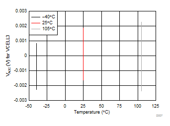
| VBAT = 27 V |
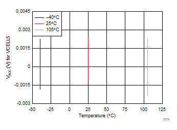
| VBAT = 27 V |
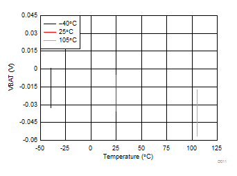
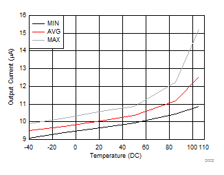
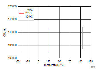
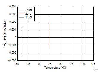
| VBAT = 27 V |
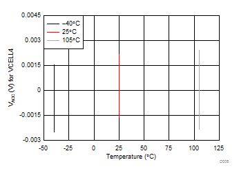
| VBAT = 27 V |
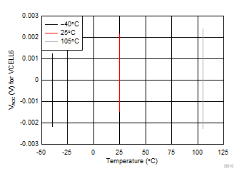
| VBAT = 27 V |
