ZHCSR27D August 2020 – September 2022 BQ79612-Q1 , BQ79614-Q1 , BQ79616-Q1
PRODUCTION DATA
- 1 特性
- 2 应用
- 3 说明
- 4 Revision History
- 5 说明(续)
- 6 Device Comparison Table
- 7 Pin Configuration and Functions
- 8 Specifications
-
9 Detailed Description
- 9.1 Overview
- 9.2 Functional Block Diagram
- 9.3
Feature Description
- 9.3.1 Power Supplies
- 9.3.2 Measurement System
- 9.3.3 Cell Balancing
- 9.3.4 Integrated Hardware Protectors
- 9.3.5 GPIO Configuration
- 9.3.6
Communication, OTP, Diagnostic Control
- 9.3.6.1
Communication
- 9.3.6.1.1 Serial Interface
- 9.3.6.1.2 Daisy Chain Interface
- 9.3.6.1.3 Start Communication
- 9.3.6.1.4 Communication Timeout
- 9.3.6.1.5 Communication Debug Mode
- 9.3.6.1.6 Multidrop Configuration
- 9.3.6.1.7 SPI Master
- 9.3.6.1.8 SPI Loopback
- 9.3.6.2 Fault Handling
- 9.3.6.3 Nonvolatile Memory
- 9.3.6.4 Diagnostic Control/Status
- 9.3.6.1
Communication
- 9.3.7 Bus Bar Support
- 9.4 Device Functional Modes
- 9.5
Register Maps
- 9.5.1 OTP Shadow Register Summary
- 9.5.2 Read/Write Register Summary
- 9.5.3 Read-Only Register Summary
- 9.5.4
Register Field Descriptions
- 9.5.4.1 Device Addressing Setup
- 9.5.4.2 Device ID and Scratch Pad
- 9.5.4.3
General Configuration and Control
- 9.5.4.3.1 DEV_CONF
- 9.5.4.3.2 ACTIVE_CELL
- 9.5.4.3.3 BBVC_POSN1
- 9.5.4.3.4 BBVC_POSN2
- 9.5.4.3.5 PWR_TRANSIT_CONF
- 9.5.4.3.6 COMM_TIMEOUT_CONF
- 9.5.4.3.7 TX_HOLD_OFF
- 9.5.4.3.8 STACK_RESPONSE
- 9.5.4.3.9 BBP_LOC
- 9.5.4.3.10 COMM_CTRL
- 9.5.4.3.11 CONTROL1
- 9.5.4.3.12 CONTROL2
- 9.5.4.3.13 CUST_CRC_HI
- 9.5.4.3.14 CUST_CRC_LO
- 9.5.4.3.15 CUST_CRC_RSLT_HI
- 9.5.4.3.16 CUST_CRC_RSLT_LO
- 9.5.4.4 Operation Status
- 9.5.4.5 ADC Configuration and Control
- 9.5.4.6
ADC Measurement Results
- 9.5.4.6.1 VCELL16_HI/LO
- 9.5.4.6.2 VCELL15_HI/LO
- 9.5.4.6.3 VCELL14_HI/LO
- 9.5.4.6.4 VCELL13_HI/LO
- 9.5.4.6.5 VCELL12_HI/LO
- 9.5.4.6.6 VCELL11_HI/LO
- 9.5.4.6.7 VCELL10_HI/LO
- 9.5.4.6.8 VCELL9_HI/LO
- 9.5.4.6.9 VCELL8_HI/LO
- 9.5.4.6.10 VCELL7_HI/LO
- 9.5.4.6.11 VCELL6_HI/LO
- 9.5.4.6.12 VCELL5_HI/LO
- 9.5.4.6.13 VCELL4_HI/LO
- 9.5.4.6.14 VCELL3_HI/LO
- 9.5.4.6.15 VCELL2_HI/LO
- 9.5.4.6.16 VCELL1_HI/LO
- 9.5.4.6.17 BUSBAR_HI/LO
- 9.5.4.6.18 TSREF_HI/LO
- 9.5.4.6.19 GPIO1_HI/LO
- 9.5.4.6.20 GPIO2_HI/LO
- 9.5.4.6.21 GPIO3_HI/LO
- 9.5.4.6.22 GPIO4_HI/LO
- 9.5.4.6.23 GPIO5_HI/LO
- 9.5.4.6.24 GPIO6_HI/LO
- 9.5.4.6.25 GPIO7_HI/LO
- 9.5.4.6.26 GPIO8_HI/LO
- 9.5.4.6.27 DIETEMP1_HI/LO
- 9.5.4.6.28 DIETEMP2_HI/LO
- 9.5.4.6.29 AUX_CELL_HI/LO
- 9.5.4.6.30 AUX_GPIO_HI/LO
- 9.5.4.6.31 AUX_BAT_HI/LO
- 9.5.4.6.32 AUX_REFL_HI/LO
- 9.5.4.6.33 AUX_VBG2_HI/LO
- 9.5.4.6.34 AUX_AVAO_REF_HI/LO
- 9.5.4.6.35 AUX_AVDD_REF_HI/LO
- 9.5.4.6.36 AUX_OV_DAC_HI/LO
- 9.5.4.6.37 AUX_UV_DAC_HI/LO
- 9.5.4.6.38 AUX_OT_OTCB_DAC_HI/LO
- 9.5.4.6.39 AUX_UT_DAC_HI/LO
- 9.5.4.6.40 AUX_VCBDONE_DAC_HI/LO
- 9.5.4.6.41 AUX_VCM_HI/LO
- 9.5.4.6.42 REFOVDAC_HI/LO
- 9.5.4.6.43 DIAG_MAIN_HI/LO
- 9.5.4.6.44 DIAG_AUX_HI/LO
- 9.5.4.7 Balancing Configuration, Control and Status
- 9.5.4.8 Protector Configuration and Control
- 9.5.4.9 GPIO Configuration
- 9.5.4.10 SPI Master
- 9.5.4.11 Diagnostic Control
- 9.5.4.12 Fault Configuration and Reset
- 9.5.4.13
Fault Status
- 9.5.4.13.1 FAULT_SUMMARY
- 9.5.4.13.2 FAULT_COMM1
- 9.5.4.13.3 FAULT_COMM2
- 9.5.4.13.4 FAULT_COMM3
- 9.5.4.13.5 FAULT_OTP
- 9.5.4.13.6 FAULT_SYS
- 9.5.4.13.7 FAULT_PROT1
- 9.5.4.13.8 FAULT_PROT2
- 9.5.4.13.9 FAULT_OV1
- 9.5.4.13.10 FAULT_OV2
- 9.5.4.13.11 FAULT_UV1
- 9.5.4.13.12 FAULT_UV2
- 9.5.4.13.13 FAULT_OT
- 9.5.4.13.14 FAULT_UT
- 9.5.4.13.15 FAULT_COMP_GPIO
- 9.5.4.13.16 FAULT_COMP_VCCB1
- 9.5.4.13.17 FAULT_COMP_VCCB2
- 9.5.4.13.18 FAULT_COMP_VCOW1
- 9.5.4.13.19 FAULT_COMP_VCOW2
- 9.5.4.13.20 FAULT_COMP_CBOW1
- 9.5.4.13.21 FAULT_COMP_CBOW2
- 9.5.4.13.22 FAULT_COMP_CBFET1
- 9.5.4.13.23 FAULT_COMP_CBFET2
- 9.5.4.13.24 FAULT_COMP_MISC
- 9.5.4.13.25 FAULT_PWR1
- 9.5.4.13.26 FAULT_PWR2
- 9.5.4.13.27 FAULT_PWR3
- 9.5.4.14
Debug Control and Status
- 9.5.4.14.1 DEBUG_CTRL_UNLOCK
- 9.5.4.14.2 DEBUG_COMM_CTRL1
- 9.5.4.14.3 DEBUG_COMM_CTRL2
- 9.5.4.14.4 DEBUG_COMM_STAT
- 9.5.4.14.5 DEBUG_UART_RC
- 9.5.4.14.6 DEBUG_UART_RR_TR
- 9.5.4.14.7 DEBUG_COMH_BIT
- 9.5.4.14.8 DEBUG_COMH_RC
- 9.5.4.14.9 DEBUG_COMH_RR_TR
- 9.5.4.14.10 DEBUG_COML_BIT
- 9.5.4.14.11 DEBUG_COML_RC
- 9.5.4.14.12 DEBUG_COML_RR_TR
- 9.5.4.14.13 DEBUG_UART_DISCARD
- 9.5.4.14.14 DEBUG_COMH_DISCARD
- 9.5.4.14.15 DEBUG_COML_DISCARD
- 9.5.4.14.16 DEBUG_UART_VALID_HI/LO
- 9.5.4.14.17 DEBUG_COMH_VALID_HI/LO
- 9.5.4.14.18 DEBUG_COML_VALID_HI/LO
- 9.5.4.14.19 DEBUG_OTP_SEC_BLK
- 9.5.4.14.20 DEBUG_OTP_DED_BLK
- 9.5.4.15
OTP Programming Control and Status
- 9.5.4.15.1 OTP_PROG_UNLOCK1A through OTP_PROG_UNLOCK1D
- 9.5.4.15.2 OTP_PROG_UNLOCK2A through OTP_PROG_UNLOCK2D
- 9.5.4.15.3 OTP_PROG_CTRL
- 9.5.4.15.4 OTP_ECC_TEST
- 9.5.4.15.5 OTP_ECC_DATAIN1 through OTP_ECC_DATAIN9
- 9.5.4.15.6 OTP_ECC_DATAOUT1 through OTP_ECC_DATAOUT9
- 9.5.4.15.7 OTP_PROG_STAT
- 9.5.4.15.8 OTP_CUST1_STAT
- 9.5.4.15.9 OTP_CUST2_STAT
-
10Application and Implementation
- 10.1 Application Information
- 10.2
Typical Applications
- 10.2.1
Base
Device Application Circuit
- 10.2.1.1 Design Requirements
- 10.2.1.2 Detailed Design Procedure
- 10.2.1.3 Application Curve
- 10.2.2 Daisy Device Application Circuit
- 10.2.1
Base
Device Application Circuit
- 11Power Supply Recommendations
- 12Layout
- 13Device and Documentation Support
- 14Mechanical, Packaging, and Orderable Information
9.3.4.2.1 OTUT Operation Modes
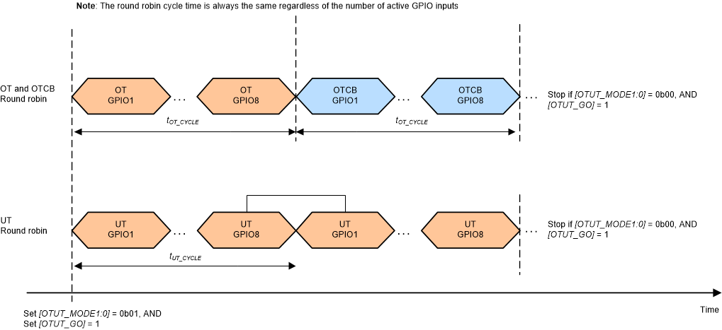
The OT and UT protectors have several operation modes controlled by OTUT_CTRL[OTUT_MODE1:0] and are summarized in Table 9-8. To start the OTUT protectors, the MCU sets OTUT_CTRL[OTUT_GO] = 1.
Table 9-8 OTUT Protector Operation Modes
| [OTUT_MOD1:0] | Operation Mode | Description |
|---|---|---|
| 0b00 | Stop OT and UT protectors | Stop OT and UT protectors |
| 0b01 | Round robin run | The OT and UT protectors are looping through all GPIO inputs. The active GPIO inputs are checked against the OT and UT thresholds (Figure 9-22). The round robin cycle timing is always the same regardless of the number of the active GPIOs. For the inactive GPIO inputs, the digital logic simply ignores the detection outcome. The OT protector detects both OT threshold and OTCB threshold. |
| 0b10 | OT and UT BIST run (diagnostic use, see Section 9.3.6.4 for details) | A BIST (built-in self-test) cycle on the OT and UT comparators and the detection paths. Temperature (GPIO channels) ADC measurement from the main or AUX ADC and the OT and UT detections through the OTUT protectors are not available during this run. |
| 0b11 | Single channel run (diagnostic use, see Section 9.3.6.4 for details) | Used for checking the OT and UT DACs. The OT and UT comparator is locked to a single GPIO input channel in this mode. Channel is locked by OTUT_CTRL[OTUT_LOCK2:0]. |
 Figure 9-22 OT and UT Round Robin Modes