ZHCSOT4B February 2020 – May 2021 CC3230S , CC3230SF
PRODUCTION DATA
- 1 特性
- 2 应用
- 3 说明
- 4 功能方框图
- 5 Revision History
- 6 Device Comparison
- 7 Terminal Configuration and Functions
-
8 Specifications
- 8.1 Absolute Maximum Ratings
- 8.2 ESD Ratings
- 8.3 Power-On Hours (POH)
- 8.4 Recommended Operating Conditions
- 8.5 Current Consumption Summary (CC3230S)
- 8.6 Current Consumption Summary (CC3230SF)
- 8.7 TX Power Control
- 8.8 Brownout and Blackout Conditions
- 8.9 Electrical Characteristics for GPIO Pins
- 8.10 Electrical Characteristics for Pin Internal Pullup and Pulldown
- 8.11 WLAN Receiver Characteristics
- 8.12 WLAN Transmitter Characteristics
- 8.13 WLAN Transmitter Out-of-Band Emissions
- 8.14 BLE/2.4 GHz Radio Coexistence and WLAN Coexistence Requirements
- 8.15 Thermal Resistance Characteristics for RGK Package
- 8.16
Timing and Switching Characteristics
- 8.16.1 Power Supply Sequencing
- 8.16.2 Device Reset
- 8.16.3 Reset Timing
- 8.16.4 Wakeup From HIBERNATE Mode
- 8.16.5 Clock Specifications
- 8.16.6 Peripherals Timing
- 9 Detailed Description
- 10Applications, Implementation, and Layout
- 11Device and Documentation Support
- 12Mechanical, Packaging, and Orderable Information
10.2.2.1 Design Considerations
The following design guidelines must be followed when laying out the CC3230x device:
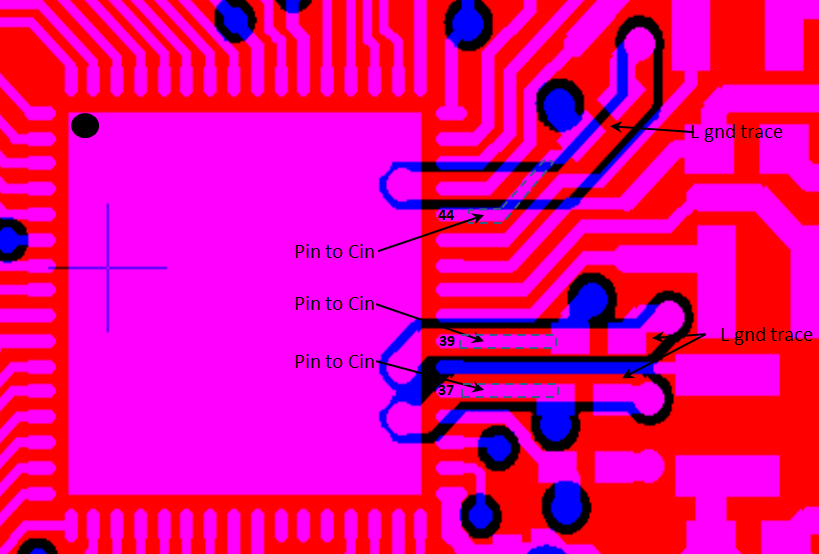
- Ground returns of the input decoupling capacitors (C11, C13, and C19) should be routed on Layer 2 using thick traces to isolate the RF ground from the noisy supply ground. This step is also required to meet the IEEE spectral mask specifications.
- Maintain the thickness of power traces to be greater than 12 mils. Take special consideration for power amplifier supply lines (pin 33, 40, 41, and 42), and all input supply pins (pin 37, 39, and 44).
- Ensure the shortest grounding loop for the PLL supply decoupling capacitor (pin 24).
- Place all decoupling capacitors as close to the respective pins as possible.
- Power budget—the CC3230x device can consume up to 450 mA for 3.3 V, 670 mA for 2.1 V, for
24 ms during the calibration cycle. - Ensure the power supply is designed to source this current without any issues. The complete calibration (TX and RX) can take up to 17 mJ of energy from the battery over a time of 24 ms.
- The CC3230x device contains many high-current
input pins. Ensure the trace feeding these pins can handle the following
currents:
- VIN_DCDC_PA input (pin 39) maximum 1 A
- VIN_DCDC_ANA input (pin 37) maximum 600 mA
- VIN_DCDC_DIG input (pin 44) maximum 500 mA
- DCDC_PA_SW_P (pin 40) and DCDC_PA_SW_N (pin 41) switching nodes maximum 1 A
- DCDC_PA_OUT output node (pin 42) maximum 1 A
- DCDC_ANA_SW switching node (pin 38) maximum 600 mA
- DCDC_DIG_SW switching node (pin 43) maximum 500 mA
- VDD_PA_IN supply (pin 33) maximum 500 mA
 Figure 10-6 Ground Returns for Input Capacitors