ZHCSAO1D January 2013 – August 2016 CSD97374Q4M
7.4 PWM Pin
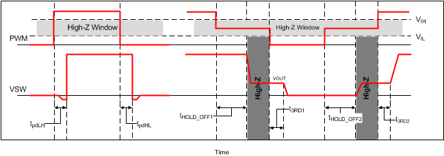
The PWM pin incorporates an input tri-state function. The device forces the gate driver outputs to low when PWM is driven into the tri-state window and the driver enters a low-power state with zero exit latency. The pin incorporates a weak pullup to maintain the voltage within the tri-state window during low-power modes. Operation into and out of tri-state mode follows the timing diagram outlined in Figure 13.
When VDD reaches the UVLO_H level, a tri-state voltage range (window) is set for the PWM input voltage. The window is defined the PWM voltage range between PWM logic high (VIH) and logic low (VIL) thresholds. The device sets high-level input voltage and low-level input voltage threshold levels to accommodate both 3.3-V (typical) and 5-V (typical) PWM drive signals.
When the PWM exits tri-state, the driver enters CCM for a period of 4 µs, regardless of the state of the SKIP# pin. Normal operation requires this time period in order for the auto-zero comparator to resume.
 Figure 13. PWM Tri-State Timing Diagram