ZHCSHU4E April   2005  – March 2018 DAC7811

PRODUCTION DATA.  

  1. 特性
  2. 应用
  3. 说明
    1.     Device Images
      1.      框图
  4. 修订历史记录
  5. Pin Configuration and Functions
    1.     Pin Functions
  6. Specifications
    1. 6.1 Absolute Maximum Ratings
    2. 6.2 ESD Ratings
    3. 6.3 Recommended Operating Conditions
    4. 6.4 Thermal Information
    5. 6.5 Electrical Characteristics
    6. 6.6 Typical Characteristics: VDD = 5 V
    7. 6.7 Typical Characteristics: VDD = 2.7 V
  7. Detailed Description
    1. 7.1 Overview
    2. 7.2 Functional Block Diagram
    3. 7.3 Feature Description
    4. 7.4 Device Functional Modes
      1. 7.4.1 Serial Interface
      2. 7.4.2 Input Shift Register
      3. 7.4.3 SYNC Interrupt (Stand-Alone Mode)
      4. 7.4.4 Daisy-Chain
      5. 7.4.5 Control Bits C3 to C0
  8. Application and Implementation
    1. 8.1 Application Information
      1. 8.1.1 Unipolar Operation Using DAC7811
      2. 8.1.2 Bipolar Operation Using the DAC7811
      3. 8.1.3 Stability Circuit
      4. 8.1.4 Amplifier Selection
      5. 8.1.5 Programmable Current Source Circuit
    2. 8.2 Typical Application
      1. 8.2.1 Single Supply Unipolar Multiplying DAC
        1. 8.2.1.1 Design Requirements
        2. 8.2.1.2 Detailed Design Procedure
        3. 8.2.1.3 Application Curve
  9. Power Supply Recommendations
  10. 10Layout
    1. 10.1 Layout Guidelines
    2. 10.2 Layout Example
  11. 11器件和文档支持
    1. 11.1 文档支持
      1. 11.1.1 相关文档
    2. 11.2 接收文档更新通知
    3. 11.3 社区资源
    4. 11.4 商标
    5. 11.5 静电放电警告
    6. 11.6 Glossary
  12. 12机械、封装和可订购信息

封装选项

机械数据 (封装 | 引脚)
散热焊盘机械数据 (封装 | 引脚)
订购信息

Daisy-Chain

The DAC7811 powers up in the daisy-chain mode which must be used when two or more devices are connected in tandem. The SCLK and SYNC signals are shared across all devices while the SDO output of the first device connects to the SDIN input of the following device, and so forth. In this configuration 16 SCLK cycles for each DAC7811 in the chain are required. Please refer to the timing diagram of Figure 27.

For n devices in a daisy-chain configuration, 16n SCLK cycles are required to shift in the entire input data stream. After 16n active SCLK edges are received following a falling SYNC, the data stream becomes complete, and SYNC can brought high to update n devices simultaneously.

When SYNC is brought high, each device will execute the function defined by the four DAC control bits C3-C0 in its input shift register. For example, C3-C0 must be 0001 for each DAC in the chain that is to be updated with new data, and C3-C0 must be 0000 for each DAC in the chain whose contents are to remain unchanged.

A continuous stream containing the exact number of SCLK cycles may be sent first while the SYNC signal is held low, and then raise SYNC at a later time. Nothing happens until the rising edge of SYNC, and then each DAC7811 in the chain will execute the function defined by the four DAC control bits C3-C0 in its input shift register.
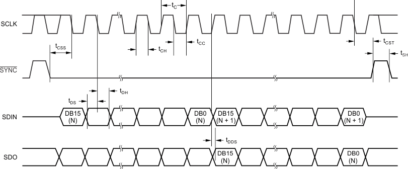
DAC7811 dac7811-timing-diagram.gifFigure 27. DAC7811 Timing Diagram