ZHCSBX4D June 2013 – December 2021 DAC7760 , DAC8760
PRODUCTION DATA
- 1 特性
- 2 应用
- 3 说明
- 4 Revision History
- 5 Device Comparison Table
- 6 Pin Configuration and Functions
- 7 Specifications
- 8 Detailed Description
- 9 Application and Implementation
- 10Power Supply Recommendations
- 11Layout
- 12Device and Documentation Support
- 13Mechanical, Packaging, and Orderable Information
封装选项
机械数据 (封装 | 引脚)
散热焊盘机械数据 (封装 | 引脚)
订购信息
9.2.3 Application Curves
The current output circuit was
measured in 0-mA to 24-mA mode using an 8.5 digit digital multi-meter to measure the
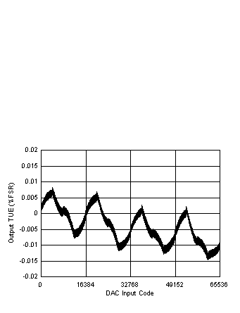
output while driving a 300-Ω load at 25°C. The measured results are shown in Figure 9-8. The voltage output circuit was measured in ±10-V mode using an 8.5 digit digital
multi-meter to measure the output while driving a
1-kΩ load at 25°C. The measured results are shown in Figure 9-9. In both cases, the voltage and current outputs remain within the specified
performance of the data sheet.
The design was also exposed to IEC61000-4 electrostatic discharge, electrically fast transient, conducted immunity, and radiated immunity tests on both the current and voltage outputs. During each of these tests a 6.5 digit digital multi-meter, set in fast 5.5 digit acquisition mode, was used to monitor the outputs. Complete data sets for the voltage and current outputs during these tests are available in TIPD153.
 Figure 9-8 Voltage Output TUE Versus Code
 Figure 9-9 Current Output TUE Versus Code