ZHCSD21 October   2014 DLP6500FLQ

PRODUCTION DATA.  

  1. 特性
  2. 应用
  3. 说明
  4. 修订历史记录
  5. Pin Configuration and Functions
  6. Specifications
    1. 6.1  Absolute Maximum Ratings
    2. 6.2  Handling Ratings
    3. 6.3  Recommended Operating Conditions
    4. 6.4  Thermal Information
    5. 6.5  Electrical Characteristics
    6. 6.6  Timing Requirements
    7. 6.7  Typical Characteristics
    8. 6.8  System Mounting Interface Loads
    9. 6.9  Micromirror Array Physical Characteristics
    10. 6.10 Micromirror Array Optical Characteristics
    11. 6.11 Window Characteristics
    12. 6.12 Chipset Component Usage Specification
  7. Detailed Description
    1. 7.1 Overview
    2. 7.2 Functional Block Diagram
    3. 7.3 Feature Description
    4. 7.4 Device Functional Modes
    5. 7.5 Window Characteristics and Optics
      1. 7.5.1 Optical Interface and System Image Quality
      2. 7.5.2 Numerical Aperture and Stray Light Control
      3. 7.5.3 Pupil Match
      4. 7.5.4 Illumination Overfill
    6. 7.6 Micromirror Array Temperature Calculation
    7. 7.7 Micromirror Landed-on/Landed-Off Duty Cycle
      1. 7.7.1 Definition of Micromirror Landed-On/Landed-Off Duty Cycle
      2. 7.7.2 Landed Duty Cycle and Useful Life of the DMD
      3. 7.7.3 Landed Duty Cycle and Operational DMD Temperature
      4. 7.7.4 Estimating the Long-Term Average Landed Duty Cycle of a Product or Application
  8. Application and Implementation
    1. 8.1 Application Information
    2. 8.2 Typical Application
      1. 8.2.1 Design Requirements
      2. 8.2.2 Detailed Design Procedure
  9. Power Supply Recommendations
    1. 9.1 DMD Power Supply Requirements
    2. 9.2 DMD Power Supply Power-Up Procedure
    3. 9.3 DMD Power Supply Power-Down Procedure
  10. 10Layout
    1. 10.1 Layout Guidelines
      1. 10.1.1 General PCB Recommendations
    2. 10.2 Layout Example
      1. 10.2.1 Board Stack and Impedance Requirements
        1. 10.2.1.1 Power Planes
        2. 10.2.1.2 LVDS Signals
        3. 10.2.1.3 Critical Signals
        4. 10.2.1.4 Flex Connector Plating
        5. 10.2.1.5 Device Placement
        6. 10.2.1.6 Device Orientation
        7. 10.2.1.7 Fiducials
  11. 11器件和文档支持
    1. 11.1 器件支持
      1. 11.1.1 器件命名规则
      2. 11.1.2 器件标记
    2. 11.2 文档支持
      1. 11.2.1 相关文档 
    3. 11.3 商标
    4. 11.4 静电放电警告
    5. 11.5 术语表
  12. 12机械封装和可订购信息

封装选项

请参考 PDF 数据表获取器件具体的封装图。

机械数据 (封装 | 引脚)
  • FLQ|203
散热焊盘机械数据 (封装 | 引脚)
订购信息

11 器件和文档支持

11.1 器件支持

11.1.1 器件命名规则

Table 9. 封装具体信息

封装类型 引脚 连接器
FLQ 203 LGA
Part_Number_DLP6500FLQ.gifFigure 19. 部件号说明

11.1.2 器件标记

器件标记将包括可读信息和一个二维矩阵码。 Figure 20 中显示了可读信息。 二维矩阵码是一个字母数字字符串,其中包含 DMD 部件号、序列号的第 1 部分和序列号的第 2 部分。 DMD 序列号(第 1 部分)的首字符为制造年份。 DMD 序列号(第 1 部分)的第二个字符为制造月份。 DMD 序列号(第 2 部分)的最后一个字符为偏置电压二进制字母。
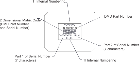
typa_2nd.gifFigure 20. DMD 标记位置

11.2 文档支持

11.2.1 相关文档 

以下文档包含关于使用 DLP6500 器件的更多信息。

Table 10. 相关文档

文档
DLPC900 数字控制器数据表 DLPS037
DLPC900 软件编程人员指南 DLPU018

11.3 商标

DLP is a trademark of Texas Instruments.

All other trademarks are the property of their respective owners.

11.4 静电放电警告

esds-image

这些装置包含有限的内置 ESD 保护。 存储或装卸时,应将导线一起截短或将装置放置于导电泡棉中,以防止 MOS 门极遭受静电损伤。

11.5 术语表

SLYZ022TI 术语表

这份术语表列出并解释术语、首字母缩略词和定义。