ZHCSD21 October   2014 DLP6500FLQ

PRODUCTION DATA.  

  1. 特性
  2. 应用
  3. 说明
  4. 修订历史记录
  5. Pin Configuration and Functions
  6. Specifications
    1. 6.1  Absolute Maximum Ratings
    2. 6.2  Handling Ratings
    3. 6.3  Recommended Operating Conditions
    4. 6.4  Thermal Information
    5. 6.5  Electrical Characteristics
    6. 6.6  Timing Requirements
    7. 6.7  Typical Characteristics
    8. 6.8  System Mounting Interface Loads
    9. 6.9  Micromirror Array Physical Characteristics
    10. 6.10 Micromirror Array Optical Characteristics
    11. 6.11 Window Characteristics
    12. 6.12 Chipset Component Usage Specification
  7. Detailed Description
    1. 7.1 Overview
    2. 7.2 Functional Block Diagram
    3. 7.3 Feature Description
    4. 7.4 Device Functional Modes
    5. 7.5 Window Characteristics and Optics
      1. 7.5.1 Optical Interface and System Image Quality
      2. 7.5.2 Numerical Aperture and Stray Light Control
      3. 7.5.3 Pupil Match
      4. 7.5.4 Illumination Overfill
    6. 7.6 Micromirror Array Temperature Calculation
    7. 7.7 Micromirror Landed-on/Landed-Off Duty Cycle
      1. 7.7.1 Definition of Micromirror Landed-On/Landed-Off Duty Cycle
      2. 7.7.2 Landed Duty Cycle and Useful Life of the DMD
      3. 7.7.3 Landed Duty Cycle and Operational DMD Temperature
      4. 7.7.4 Estimating the Long-Term Average Landed Duty Cycle of a Product or Application
  8. Application and Implementation
    1. 8.1 Application Information
    2. 8.2 Typical Application
      1. 8.2.1 Design Requirements
      2. 8.2.2 Detailed Design Procedure
  9. Power Supply Recommendations
    1. 9.1 DMD Power Supply Requirements
    2. 9.2 DMD Power Supply Power-Up Procedure
    3. 9.3 DMD Power Supply Power-Down Procedure
  10. 10Layout
    1. 10.1 Layout Guidelines
      1. 10.1.1 General PCB Recommendations
    2. 10.2 Layout Example
      1. 10.2.1 Board Stack and Impedance Requirements
        1. 10.2.1.1 Power Planes
        2. 10.2.1.2 LVDS Signals
        3. 10.2.1.3 Critical Signals
        4. 10.2.1.4 Flex Connector Plating
        5. 10.2.1.5 Device Placement
        6. 10.2.1.6 Device Orientation
        7. 10.2.1.7 Fiducials
  11. 11器件和文档支持
    1. 11.1 器件支持
      1. 11.1.1 器件命名规则
      2. 11.1.2 器件标记
    2. 11.2 文档支持
      1. 11.2.1 相关文档 
    3. 11.3 商标
    4. 11.4 静电放电警告
    5. 11.5 术语表
  12. 12机械封装和可订购信息

封装选项

请参考 PDF 数据表获取器件具体的封装图。

机械数据 (封装 | 引脚)
  • FLQ|203
散热焊盘机械数据 (封装 | 引脚)
订购信息

1 特性

  • 高分辨率 1080p (1920×1080) 阵列,
    微镜数超过 2 百万
    • 0.65 英寸微镜阵列对角线
    • 7.56µm 微镜间距
    • ±12° 微镜倾斜角(相对于平面)
    • 2.5µs 微镜交叉时间
    • 设计用于边缘照明
  • 设计用于宽频带可见光 (400nm – 700nm)
    • 窗口传输 97%(单通、通过双窗面)
    • 微镜反射率 88%
    • 阵列衍射效率 86%
    • 阵列填充因子 92%
  • 两条 16 位低压差分信令 (LVDS)、双倍数据速率 (DDR) 输入数据总线
  • 专用 DLPC900 控制器,支持 9500Hz(1 位二进制)和 250Hz(8 位灰度)高速模式速率
  • 高达 400MHz 的输入数据时钟速率
  • 集成微镜驱动器电路
  • 气密封装

2 应用

  • 工业
    • 针对机器视觉和质量控制的 3D 扫描仪
    • 3D 打印
    • 直接成像平版印刷术
    • 激光打标和修复
  • 医疗
    • 眼科
    • 针对四肢和皮肤测量的 3D 扫描仪
    • 高光谱成像
  • 显示屏
    • 3D 成像显微镜
    • 智能和自适应照明

3 说明

高分辨率 0.65 1080p 数字微镜器件 (DMD) 是一款可调制入射光幅度、方向和位相的空间照明调制器 (SLM),其采用气密封装,微镜数达 2 百万以上。 DLP6500FLQ 具有独特的功能和价值(包括在 405nm 波长下工作),非常适用于广泛的工业、医疗和高级成像应用。 DLP6500FLQ 需要与 DLPC900 数字控制器结合使用才能实现可靠功能和操作。 此专用芯片组可在高速条件下提供全高清 (HD) 分辨率,并且能够轻松集成到多种终端设备解决方案中。

器件信息(1)

器件型号 封装 封装尺寸(标称值)
DLP6500 FLQ (203) 40.6mm × 31.8mm × 6mm
  1. 如需了解所有可用封装,请见数据表末尾的可订购米6体育平台手机版_好二三四附录。

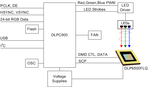
简化图表
DLP6500FLQ_typdia.gif

4 修订历史记录

日期 修订版本 注释
2014 年 10 月 * 最初发布。