ZHCSKV8A November   2020  – June 2022 DLP670S

PRODUCTION DATA  

  1. 特性
  2. 应用
  3. 说明
  4. Revision History
  5. Pin Configuration and Functions
  6. Specifications
    1. 6.1  Absolute Maximum Ratings
    2. 6.2  Storage Conditions
    3. 6.3  ESD Ratings
    4. 6.4  Recommended Operating Conditions
    5. 6.5  Thermal Information
    6. 6.6  Electrical Characteristics
    7. 6.7  Capacitance at Recommended Operating Conditions
    8. 6.8  Timing Requirements
    9. 6.9  Typical Characteristics
    10. 6.10 System Mounting Interface Loads
    11. 6.11 Micromirror Array Physical Characteristics
    12. 6.12 Micromirror Array Optical Characteristics
    13. 6.13 Window Characteristics
    14. 6.14 Chipset Component Usage Specification
  7. Detailed Description
    1. 7.1 Overview
    2. 7.2 Functional Block Diagram
    3. 7.3 Feature Description
      1. 7.3.1 Power Interface
      2. 7.3.2 Timing
    4. 7.4 Device Functional Modes
    5. 7.5 Optical Interface and System Image Quality
      1. 7.5.1 Numerical Aperture and Stray Light Control
      2. 7.5.2 Pupil Match
      3. 7.5.3 Illumination Overfill
    6. 7.6 Micromirror Array Temperature Calculation
      1. 7.6.1 Micromirror Array Temperature Calculation using Illumination Power Density
      2. 7.6.2 Micromirror Array Temperature Calculation using Total Illumination Power
      3. 7.6.3 Micromirror Array Temperature Calculation using Screen Lumens
    7. 7.7 Micromirror Landed-On/Landed-Off Duty Cycle
      1. 7.7.1 Definition of Micromirror Landed-On/Landed-Off Duty Cycle
      2. 7.7.2 Landed Duty Cycle and Useful Life of the DMD
      3. 7.7.3 Landed Duty Cycle and Operational DMD Temperature
      4. 7.7.4 Estimating the Long-Term Average Landed Duty Cycle of a Product or Application
  8. Application and Implementation
    1. 8.1 Application Information
    2. 8.2 Typical Application
      1. 8.2.1 Design Requirements
      2. 8.2.2 Detailed Design Procedure
    3. 8.3 DMD Die Temperature Sensing
  9. Power Supply Recommendations
    1. 9.1 DMD Power Supply Power-Up Procedure
    2. 9.2 DMD Power Supply Power-Down Procedure
    3. 9.3 Restrictions on Hot Plugging and Hot Swapping
      1. 9.3.1 No Hot Plugging
      2. 9.3.2 No Hot Swapping
      3. 9.3.3 Intermittent or Voltage Power Spike Avoidance
  10. 10Layout
    1. 10.1 Layout Guidelines
      1. 10.1.1 Critical Signal Guidelines
      2. 10.1.2 Power Connection Guidelines
      3. 10.1.3 Noise Coupling Avoidance
    2. 10.2 Layout Example
      1. 10.2.1 Layers
      2. 10.2.2 Impedance Requirements
      3. 10.2.3 Trace Width, Spacing
        1. 10.2.3.1 Voltage Signals
  11. 11Device and Documentation Support
    1. 11.1 第三方米6体育平台手机版_好二三四免责声明
    2. 11.2 Device Support
      1. 11.2.1 Device Nomenclature
      2. 11.2.2 Device Markings
    3. 11.3 Documentation Support
      1. 11.3.1 Related Documentation
    4. 11.4 接收文档更新通知
    5. 11.5 支持资源
    6. 11.6 Trademarks
    7. 11.7 Electrostatic Discharge Caution
    8. 11.8 术语表
  12. 12Mechanical, Packaging, and Orderable Information

封装选项

机械数据 (封装 | 引脚)
散热焊盘机械数据 (封装 | 引脚)
订购信息

说明

拥有超过 430 万个微镜的 DLP670S 数字微镜器件 (DMD) 是一种空间光调制器 (SLM),调制入射光的振幅、方向和相位。此 DMD 与四条 2xLVDS 输入数据总线相结合,能够以极快的图形速率显示高分辨率图形。DLP670S 提供的高分辨率和快速图形速率使其非常适合支持各种工业、医疗和高级成像应用。DLP670S 与双 DLPC900数字控制器配合使用时可实现可靠功能和操作。此专用芯片组以满足各种终端设备解决方案要求所需的高图形速率提供灵活且易于编程的图形。

高分辨率支持扫描更大的物体,这对于 3D 机器视觉应用有直接帮助。

进入 TI DLP® 高级光控制技术页面,了解如何开始使用 DLP670STI.com 上的 DLP 先进光控制资源可加快上市速度,这些资源包括评估模块参考设计、光学模块制造商DLP 设计网络合作伙伴

表 3-1 器件信息
器件型号 封装 封装尺寸(标称值)
DLP670S(1) FYR (350) 35mm × 32mm
如需了解所有可用封装,请参阅数据表末尾的可订购米6体育平台手机版_好二三四附录。
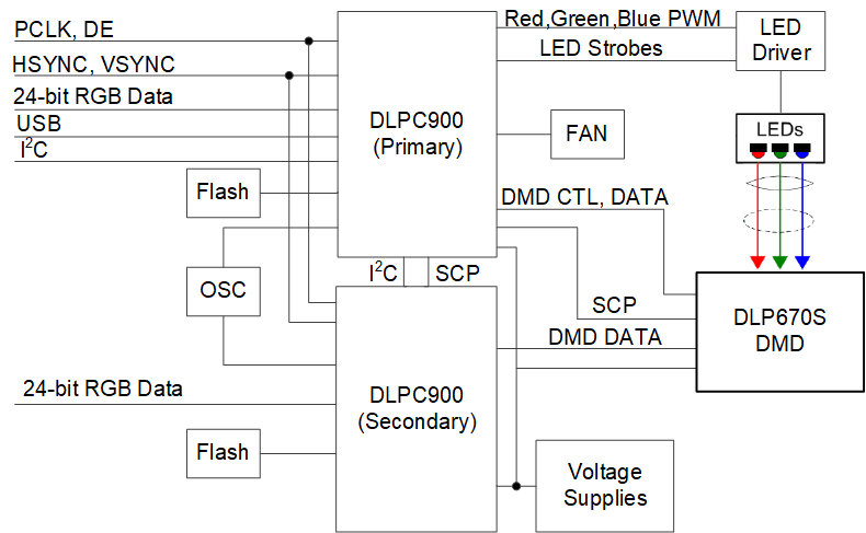
GUID-20210304-CA0I-2DJG-ZSSX-0FVPPH6PSV3C-low.pngDLP670S 简化原理图