ZHCSE87A October 2015 – September 2023 DLPA3000
PRODUCTION DATA
- 1
- 1 特性
- 2 应用
- 3 说明
- 4 Revision History
- 5 说明(续)
- 6 Pin Configuration and Functions
- 7 Specifications
-
8 Detailed Description
- 8.1 Overview
- 8.2 功能方框图
- 8.3
Feature Description
- 8.3.1 Supply and Monitoring
- 8.3.2 Illumination
- 8.3.3 DMD Supplies
- 8.3.4 Buck Converters
- 8.3.5 Auxiliary LDOs
- 8.3.6 Measurement System
- 8.3.7 Digital Control
- 8.4 Device Functional Modes
- 8.5 Register Maps
- 9 Application and Implementation
- 10Power Supply Recommendations
- 11Layout
- 12Device and Documentation Support
- 13Mechanical, Packaging, and Orderable Information
封装选项
机械数据 (封装 | 引脚)
- PFD|100
散热焊盘机械数据 (封装 | 引脚)
- PFD|100
订购信息
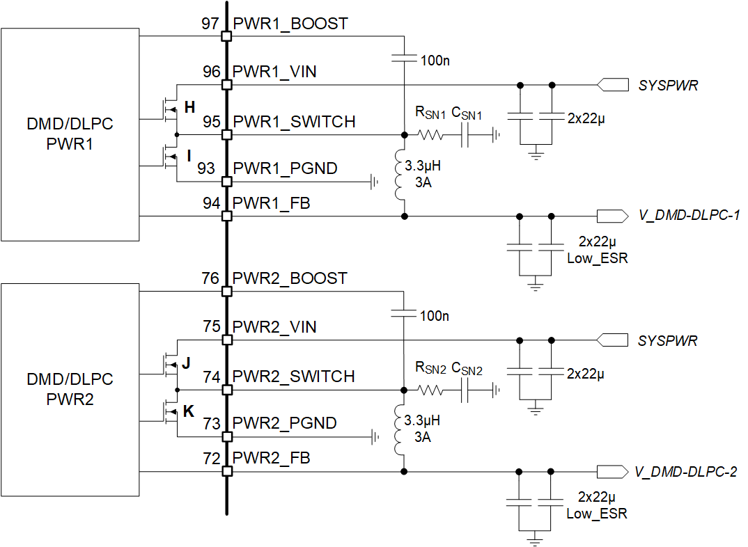
8.3.3.3 DMD/DLPC Buck Converters
Each of the two DMD buck converters creates a supply voltage for the DMD and/or the DLPC. The values of the voltages for the DMD and DLPC used, for instance:
- DMD+DLPC3438: 1.1 V (DLPC) and 1.8 V (DLPC/DMD)
The topology of the buck converters is the same as the general purpose buck converters discussed later in this document. To configure the inductor and capacitor, see Buck Converters.
A typical configuration is 3.3 µH for the inductor and 2 × 22 µF for the output capacitor. The voltage rating of the capacitor is recommended to be equal or greater than two times of the applied voltage across the capacitor in the application.
 Figure 8-19 DMD/DLPC Buck Converters