ZHCSC07E December 2013 – March 2019 DLPC2607
PRODUCTION DATA.
- 1 特性
- 2 应用范围
- 3 说明
- 4 修订历史记录
- 5 Pin Configuration and Functions
-
6 Specifications
- 6.1 Absolute Maximum Ratings
- 6.2 ESD Ratings
- 6.3 Recommended Operating Conditions
- 6.4 Thermal Information
- 6.5 Typical Current and Power Dissipation
- 6.6 I/O Characteristics
- 6.7 Internal Pullup and Pulldown Characteristics
- 6.8 Parallel I/F Frame Timing Requirements
- 6.9 Parallel I/F General Timing Requirements
- 6.10 Parallel I/F Maximum Parallel Interface Horizontal Line Rate
- 6.11 BT.656 I/F General Timing Requirements
- 6.12 100- to 120-Hz Operational Limitations
- 6.13 Flash Interface Timing Requirements
- 6.14 DMD Interface Timing Requirements
- 6.15 mDDR Memory Interface Timing Requirements
- 7 Detailed Description
- 8 Application and Implementation
- 9 Power Supply Recommendations
-
10Layout
- 10.1
Layout Guidelines
- 10.1.1 Internal ASIC PLL Power
- 10.1.2 General Handling Guidelines for Unused CMOS-Type Pins
- 10.1.3 SPI Signal Routing
- 10.1.4 mDDR Memory and DMD Interface Considerations
- 10.1.5 PCB Design
- 10.1.6 General PCB Routing (Applies to All Corresponding PCB Signals)
- 10.1.7 Maximum, Pin-to-Pin, PCB Interconnects Etch Lengths
- 10.1.8 I/F Specific PCB Routing
- 10.1.9 Number of Layer Changes
- 10.1.10 Stubs
- 10.1.11 Termination Requirements:
- 10.2 Layout Example
- 10.1
Layout Guidelines
- 11器件和文档支持
- 12机械、封装和可订购信息
请参考 PDF 数据表获取器件具体的封装图。
机械数据 (封装 | 引脚)
- ZVB|176
散热焊盘机械数据 (封装 | 引脚)
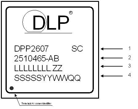
11.1.2.1 器件标记

标记定义:
- DLP 器件名称
- TI 器件型号
- LLLLLLLL.ZZ 半导体晶圆的铸造批次代码以及无铅焊锡球标记
- SSSSSYYWWQQ:封装和组装信息
SC:焊球成分
e1:表示含有 SnAgCu 的无铅焊球
G8:表示含有锡-银-铜 (SnAgCu) 的无铅焊球,其中银含量 ≤1.5% 且模压混合物符合 TI 的“绿色环保”定义
AB(1 或 2 位字母数字)=“A”对应于 TI 器件零件编号。“B”是为不合格器件标记保留的。所有不合格器件(包括原型和偏差批次样片)均在“B”标记(紧随 TI 器件型号之后)位置用“X”字母标记。合格器件的“B”标记位置留空。
LLLLLLLL:制造批次代码
ZZ:分批编号
SSSSS:制造基地
YYWW:日期代码(YY = 年 :: WW = 周)
QQ:合格等级选项 – 工程样片在该字段中以 ES 后缀标记。
例如,KOREA0914ES 是于 2009 的第 14 个周在韩国构建的工程样片。