ZHCSHH9D January 2017 – August 2021 DLPC3437
PRODUCTION DATA
- 1 特性
- 2 应用
- 3 说明
- 4 Revision History
- 5 Pin Configuration and Functions
-
6 Specifications
- 6.1 Absolute Maximum Ratings
- 6.2 ESD Ratings
- 6.3 Recommended Operating Conditions
- 6.4 Thermal Information
- 6.5 Power Electrical Characteristics
- 6.6 Pin Electrical Characteristics
- 6.7 Internal Pullup and Pulldown Electrical Characteristics
- 6.8 DMD Sub-LVDS Interface Electrical Characteristics
- 6.9 DMD Low-Speed Interface Electrical Characteristics
- 6.10 System Oscillators Timing Requirements
- 6.11 Power Supply and Reset Timing Requirements
- 6.12 Parallel Interface Frame Timing Requirements
- 6.13 Parallel Interface General Timing Requirements
- 6.14 Flash Interface Timing Requirements
- 6.15 Other Timing Requirements
- 6.16 DMD Sub-LVDS Interface Switching Characteristics
- 6.17 DMD Parking Switching Characteristics
- 6.18 Chipset Component Usage Specification
-
7 Detailed Description
- 7.1 Overview
- 7.2 Functional Block Diagram
- 7.3 Feature Description
- 7.4 Device Functional Modes
- 7.5 Programming
- 8 Application and Implementation
- 9 Power Supply Recommendations
- 10Layout
- 11Device and Documentation Support
- 12Mechanical, Packaging, and Orderable Information
7.3.1.2 3D Display
For 3D sources on the video input interface, images must be frame sequential (L, R, L, ...) when input to the DLPC34xx controller. Any processing required to unpack 3D images and to convert them to frame sequential input must be done by external electronics prior to inputting the images to the controller. Each 3D source frame input must contain a single eye frame of data, separated by a VSYNC, where an eye frame contains image data for a single left or right eye. The signal 3DR input to the controller indicates whether the input frame is for the left eye or right eye.
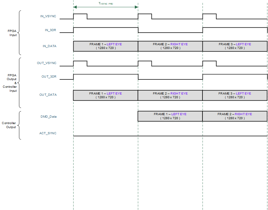
Each DMD frame is displayed at the same rate as the input interface frame rate. Figure 7-1 below shows the typical timing for a 50-Hz or 60-Hz 3D HDMI source frame, the input interface of the DLPC34xx controller, and the DMD. In general, video frames sent over the HDMI interface pack both the left and right content into the same video frame. GPIO_04 is optionally sent to a transmitter on the system PCB for wirelessly transmitting a synchronization signal to 3D glasses (usually an IR sync signal). The glasses are then in phase with the DMD images displayed. Alternately, the 3D Glasses Operation section shows how DLP link pulses can be used instead.

The frame and sub-frame timing for 2D sources is shown in Figure 7-2 while the frame and sub-frame timing for 3D sources is shown in Figure 7-3.
 Figure 7-2 DLPC3437 2D Actuator Frame and Signal Timing
 Figure 7-3 DLPC3437 3D Frame and Signal
Timing