ZHCSG69E November 2016 – May 2018 DM505
PRODUCTION DATA.
- 1器件概述
- 2修订历史记录
- 3Device Comparison
-
4Terminal Configuration and Functions
- 4.1 Pin Diagram
- 4.2 Pin Attributes
- 4.3
Signal Descriptions
- 4.3.1 VIP
- 4.3.2 DSS
- 4.3.3 SD_DAC
- 4.3.4 ADC
- 4.3.5 Camera Control
- 4.3.6 CPI
- 4.3.7 CSI2
- 4.3.8 EMIF
- 4.3.9 GPMC
- 4.3.10 Timers
- 4.3.11 I2C
- 4.3.12 UART
- 4.3.13 McSPI
- 4.3.14 QSPI
- 4.3.15 McASP
- 4.3.16 DCAN and MCAN
- 4.3.17 GMAC_SW
- 4.3.18 SDIO Controller
- 4.3.19 GPIO
- 4.3.20 ePWM
- 4.3.21 Emulation and Debug Subsystem
- 4.3.22 System and Miscellaneous
- 4.3.23 Power Supplies
- 4.4 Pin Multiplexing
- 4.5 Connections for Unused Pins
-
5Specifications
- 5.1 Absolute Maximum Ratings
- 5.2 ESD Ratings
- 5.3 Power on Hour (POH) Limits
- 5.4 Recommended Operating Conditions
- 5.5 Operating Performance Points
- 5.6 Power Consumption Summary
- 5.7
Electrical Characteristics
- Table 5-6 LVCMOS DDR DC Electrical Characteristics
- Table 5-7 Dual Voltage LVCMOS I2C DC Electrical Characteristics
- Table 5-8 IQ1833 Buffers DC Electrical Characteristics
- Table 5-9 IHHV1833 Buffers DC Electrical Characteristics
- Table 5-10 LVCMOS Analog OSC Buffers DC Electrical Characteristics
- Table 5-11 LVCMOS CSI2 DC Electrical Characteristics
- Table 5-12 Dual Voltage LVCMOS DC Electrical Characteristics
- Table 5-13 Analog-to-Digital ADC Subsystem Electrical Specifications
- 5.8 Thermal Characteristics
- 5.9
Timing Requirements and Switching Characteristics
- 5.9.1 Timing Parameters and Information
- 5.9.2 Interface Clock Specifications
- 5.9.3 Power Supply Sequences
- 5.9.4 Clock Specifications
- 5.9.5 Recommended Clock and Control Signal Transition Behavior
- 5.9.6
Peripherals
- 5.9.6.1 Timing Test Conditions
- 5.9.6.2 VIP
- 5.9.6.3 DSS
- 5.9.6.4 ISS
- 5.9.6.5 EMIF
- 5.9.6.6 GPMC
- 5.9.6.7 GP Timers
- 5.9.6.8 I2C
- 5.9.6.9 UART
- 5.9.6.10 McSPI
- 5.9.6.11 QSPI
- 5.9.6.12
McASP
- Table 5-52 Timing Requirements for McASP1
- Table 5-53 Timing Requirements for McASP2
- Table 5-54 Timing Requirements for McASP3
- Table 5-55 Switching Characteristics Over Recommended Operating Conditions for McASP1
- Table 5-56 Switching Characteristics Over Recommended Operating Conditions for McASP2
- Table 5-57 Switching Characteristics Over Recommended Operating Conditions for McASP3
- 5.9.6.13 DCAN and MCAN
- 5.9.6.14
GMAC_SW
- 5.9.6.14.1 GMAC MDIO Interface Timings
- 5.9.6.14.2
GMAC RGMII Timings
- Table 5-65 Timing Requirements for rgmiin_rxc - RGMIIn Operation
- Table 5-66 Timing Requirements for GMAC RGMIIn Input Receive for 10/100/1000 Mbps
- Table 5-67 Switching Characteristics Over Recommended Operating Conditions for rgmiin_txctl - RGMIIn Operation for 10/100/1000 Mbit/s
- Table 5-68 Switching Characteristics for GMAC RGMIIn Output Transmit for 10/100/1000 Mbps
- 5.9.6.15 SDIO Controller
- 5.9.6.16 GPIO
- 5.9.7
Emulation and Debug Subsystem
- 5.9.7.1
JTAG Electrical Data/Timing
- Table 5-79 Timing Requirements for IEEE 1149.1 JTAG
- Table 5-80 Switching Characteristics Over Recommended Operating Conditions for IEEE 1149.1 JTAG
- Table 5-81 Timing Requirements for IEEE 1149.1 JTAG With RTCK
- Table 5-82 Switching Characteristics Over Recommended Operating Conditions for IEEE 1149.1 JTAG With RTCK
- 5.9.7.2 Trace Port Interface Unit (TPIU)
- 5.9.7.1
JTAG Electrical Data/Timing
-
6Detailed Description
- 6.1 Description
- 6.2 Functional Block Diagram
- 6.3 DSP Subsystem
- 6.4 IPU
- 6.5 EVE
- 6.6 Memory Subsystem
- 6.7 Interprocessor Communication
- 6.8 Interrupt Controller
- 6.9 EDMA
- 6.10 Peripherals
- 6.11 On-Chip Debug
-
7Applications, Implementation, and Layout
- 7.1 Introduction
- 7.2 Power Optimizations
- 7.3 Core Power Domains
- 7.4 Single-Ended Interfaces
- 7.5 Differential Interfaces
- 7.6 Clock Routing Guidelines
- 7.7 LPDDR2 Board Design and Layout Guidelines
- 7.8 DDR2 Board Design and Layout Guidelines
- 7.9
DDR3 Board Design and Layout Guidelines
- 7.9.1 DDR3 General Board Layout Guidelines
- 7.9.2
DDR3 Board Design and Layout Guidelines
- 7.9.2.1 Board Designs
- 7.9.2.2 DDR3 Device Combinations
- 7.9.2.3 DDR3 Interface Schematic
- 7.9.2.4 Compatible JEDEC DDR3 Devices
- 7.9.2.5 PCB Stackup
- 7.9.2.6 Placement
- 7.9.2.7 DDR3 Keepout Region
- 7.9.2.8 Bulk Bypass Capacitors
- 7.9.2.9 High-Speed Bypass Capacitors
- 7.9.2.10 Net Classes
- 7.9.2.11 DDR3 Signal Termination
- 7.9.2.12 VTT
- 7.9.2.13 CK and ADDR_CTRL Topologies and Routing Definition
- 7.9.2.14 Data Topologies and Routing Definition
- 7.9.2.15 Routing Specification
- 7.10 CVIDEO/SD-DAC Guidelines and Electrical Data/Timing
- 8Device and Documentation Support
- 9Mechanical Packaging Information
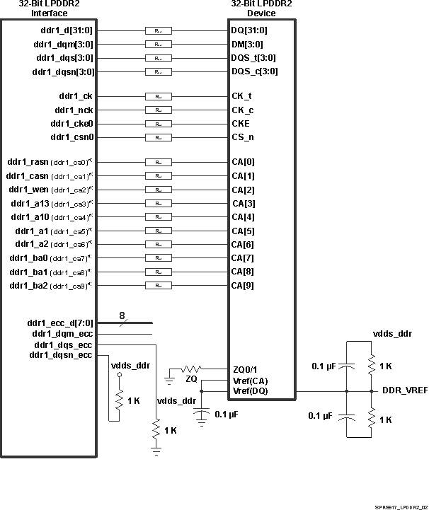
7.7.3.1 LPDDR2 Interface Schematic
Figure 7-24 shows the schematic connections for 32-bit interface with or without ECC using one x32 LPDDR2 device.
- When LPDDR2 memory are used, these signal function as ddr1_ca[9:0]. For more information, see Table 4-9, EMIF1 Signal Descriptions
- Rca is 10 Ω resistor and is to be placed near DM50x device.
- The RDAT is 22 Ω resistor and is to be placed near DM50x device
- If ECC is required, pins available behind data lane 3 (data would then only use 16bit (lanes 1 and 2))
When not using a part of LPDDR2 interface (using x16 or not using the LPDDR2 interface):
- Connect the vdds_ddr supply to 1.8 V
- Tie off ddr1_dqsx (x=0,1,2,3) that are unused to vss via 1 kΩ
- Tie off ddr1_dqsnx (x=0,1,2,3) that are unused to vdds_ddr via 1 kΩ
- All other unused pins can be left as NC.
Note: All the unused DDR ADDR_CTRL lines used for DDR3 operation should be left as NC.
