ZHCSEQ8 March   2016 DRV10964

PRODUCTION DATA.  

  1. 特性
  2. 应用范围
  3. 说明
  4. 修订历史记录
  5. Pin Configuration and Functions
  6. Specifications
    1. 6.1 Absolute Maximum Ratings
    2. 6.2 ESD Ratings
    3. 6.3 Recommended Operating Conditions
    4. 6.4 Thermal Information
    5. 6.5 Electrical Characteristics
    6. 6.6 Typical Characteristics
  7. Detailed Description
    1. 7.1 Overview
    2. 7.2 Functional Block Diagram
    3. 7.3 Feature Description
      1. 7.3.1  Sleep Mode
      2. 7.3.2  Speed Input and Control
      3. 7.3.3  Motor Direction Change
      4. 7.3.4  Motor Frequency Feedback (FG)
        1. 7.3.4.1 Tach Feedback During Spin Down
      5. 7.3.5  Lock Detection
        1. 7.3.5.1 Lock0: No Motor
        2. 7.3.5.2 Lock1: Frequency Overflow
        3. 7.3.5.3 Lock2: BEMF Abnormal
          1. 7.3.5.3.1 Lock 3: Accelerate Abnormal
        4. 7.3.5.4 Lock4: Speed Abnormal
      6. 7.3.6  Short Circuit Current Protection
      7. 7.3.7  Anti-Voltage Surge (AVS)
        1. 7.3.7.1 Protecting Against the Return of Mechanical Energy
        2. 7.3.7.2 Protecting Against the Return of Inductive Energy
      8. 7.3.8  Overtemperature Protection
      9. 7.3.9  Undervoltage Protection
      10. 7.3.10 CONFIG Configuration
    4. 7.4 Device Functional Modes
      1. 7.4.1 Spin up Settings
        1. 7.4.1.1 Motor Kt and Rm
        2. 7.4.1.2 Motor Start
        3. 7.4.1.3 Initial Speed Detect (ISD)
        4. 7.4.1.4 Align
        5. 7.4.1.5 Handoff and Closed Loop
  8. Application and Implementation
    1. 8.1 Application Information
    2. 8.2 Typical Application
      1. 8.2.1 Design Requirements
      2. 8.2.2 Detailed Design Procedure
      3. 8.2.3 Application Curves
  9. Power Supply Recommendations
  10. 10Layout
    1. 10.1 Layout Guidelines
    2. 10.2 Layout Example
  11. 11器件和文档支持
    1. 11.1 社区资源
    2. 11.2 商标
    3. 11.3 静电放电警告
    4. 11.4 Glossary
  12. 12机械、封装和可订购信息

封装选项

机械数据 (封装 | 引脚)
散热焊盘机械数据 (封装 | 引脚)
订购信息

5 Pin Configuration and Functions

DSN Package
10-Pin USON
Top View
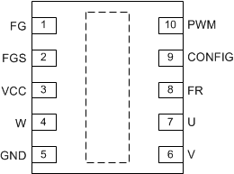
DRV10964 pin_con_drv10964.gif

Pin Functions

PIN I/O DESCRIPTION
NO. NAME
1 FG Output Motor speed indicator output (open drain).
2 FGS Input Motor speed indicator selector. The state of this pin is latched on power up and can not be changed dynamically.
3 VCC Power Input voltage for motor and chip supply.
4 W IO Motor Phase W
5 GND Ground Ground
6 V IO Motor Phase V
7 U IO Motor Phase U
8 FR Input Motor direction selector. This pin can be dynamically changed after power up.
9 CONFIG Input Resistor setting for configuring the handoff threshold. The state of this pin is latched on power up and can not be changed dynamically.
10 PWM Input Motor speed control input.
Thermal Pad Connect to Ground for maximum thermal efficiency. Thermal pad is on the bottom of the package.