ZHCSDF3D May   2014  – March 2018 DRV2605L

PRODUCTION DATA.  

  1. 特性
  2. 应用
  3. 说明
    1.     简化原理图
  4. 修订历史记录
  5. Pin Configuration and Functions
    1.     Pin Functions
    2.     Pin Functions
  6. Specifications
    1. 6.1 Absolute Maximum Ratings
    2. 6.2 ESD Ratings
    3. 6.3 Recommended Operating Conditions
    4. 6.4 Thermal Information
    5. 6.5 Electrical Characteristics
    6. 6.6 Timing Requirements
    7. 6.7 Switching Characteristics
    8. 6.8 Typical Characteristics
  7. Parameter Measurement Information
    1. 7.1 Test Setup for Graphs
      1. 7.1.1 Default Test Conditions
  8. Detailed Description
    1. 8.1 Overview
    2. 8.2 Functional Block Diagram
    3. 8.3 Feature Description
      1. 8.3.1  Support for ERM and LRA Actuators
      2. 8.3.2  Smart-Loop Architecture
        1. 8.3.2.1 Auto-Resonance Engine for LRA
        2. 8.3.2.2 Real-Time Resonance-Frequency Reporting for LRA
        3. 8.3.2.3 Automatic Switch to Open-Loop for LRA
        4. 8.3.2.4 Automatic Overdrive and Braking
          1. 8.3.2.4.1 Startup Boost
          2. 8.3.2.4.2 Brake Factor
          3. 8.3.2.4.3 Brake Stabilizer
        5. 8.3.2.5 Automatic Level Calibration
          1. 8.3.2.5.1 Automatic Compensation for Resistive Losses
          2. 8.3.2.5.2 Automatic Back-EMF Normalization
          3. 8.3.2.5.3 Calibration Time Adjustment
          4. 8.3.2.5.4 Loop-Gain Control
          5. 8.3.2.5.5 Back-EMF Gain Control
        6. 8.3.2.6 Actuator Diagnostics
        7. 8.3.2.7 Automatic Re-Synchronization
      3. 8.3.3  Open-Loop Operation for LRA
      4. 8.3.4  Open-Loop Operation for ERM
      5. 8.3.5  Flexible Front-End Interface
        1. 8.3.5.1 PWM Interface
        2. 8.3.5.2 Internal Memory Interface
          1. 8.3.5.2.1 Waveform Sequencer
          2. 8.3.5.2.2 Library Parameterization
        3. 8.3.5.3 Real-Time Playback (RTP) Interface
        4. 8.3.5.4 Analog Input Interface
        5. 8.3.5.5 Audio-to-Vibe Interface
        6. 8.3.5.6 Input Trigger Option
          1. 8.3.5.6.1 I2C Trigger
          2. 8.3.5.6.2 Edge Trigger
          3. 8.3.5.6.3 Level Trigger
        7. 8.3.5.7 Noise Gate Control
      6. 8.3.6  Edge Rate Control
      7. 8.3.7  Constant Vibration Strength
      8. 8.3.8  Battery Voltage Reporting
      9. 8.3.9  One-Time Programmable (OTP) Memory for Configuration
      10. 8.3.10 Low-Power Standby
      11. 8.3.11 I2C Watchdog Timer
      12. 8.3.12 Device Protection
        1. 8.3.12.1 Thermal Protection
        2. 8.3.12.2 Overcurrent Protection of the Actuator
        3. 8.3.12.3 Overcurrent Protection of the Regulator
        4. 8.3.12.4 Brownout Protection
    4. 8.4 Device Functional Modes
      1. 8.4.1 Power States
        1. 8.4.1.1 Operation With VDD < 2 V (Minimum VDD)
        2. 8.4.1.2 Operation With VDD > 5.5 V (Absolute Maximum VDD)
        3. 8.4.1.3 Operation With EN Control
        4. 8.4.1.4 Operation With STANDBY Control
        5. 8.4.1.5 Operation With DEV_RESET Control
        6. 8.4.1.6 Operation in the Active State
      2. 8.4.2 Changing Modes of Operation
      3. 8.4.3 Operation of the GO Bit
      4. 8.4.4 Operation During Exceptional Conditions
        1. 8.4.4.1 Operation With No Actuator Attached
        2. 8.4.4.2 Operation With a Non-Moving Actuator Attached
        3. 8.4.4.3 Operation With a Short at REG Pin
        4. 8.4.4.4 Operation With a Short at OUT+, OUT–, or Both
    5. 8.5 Programming
      1. 8.5.1 Auto-Resonance Engine Programming for the LRA
        1. 8.5.1.1 Drive-Time Programming
        2. 8.5.1.2 Current-Dissipation Time Programming
        3. 8.5.1.3 Blanking Time Programming
        4. 8.5.1.4 Zero-Crossing Detect-Time Programming
      2. 8.5.2 Automatic-Level Calibration Programming
        1. 8.5.2.1 Rated Voltage Programming
        2. 8.5.2.2 Overdrive Voltage-Clamp Programming
      3. 8.5.3 I2C Interface
        1. 8.5.3.1 General I2C Operation
        2. 8.5.3.2 Single-Byte and Multiple-Byte Transfers
        3. 8.5.3.3 Single-Byte Write
        4. 8.5.3.4 Multiple-Byte Write and Incremental Multiple-Byte Write
        5. 8.5.3.5 Single-Byte Read
        6. 8.5.3.6 Multiple-Byte Read
      4. 8.5.4 Programming for Open-Loop Operation
        1. 8.5.4.1 Programming for ERM Open-Loop Operation
        2. 8.5.4.2 Programming for LRA Open-Loop Operation
      5. 8.5.5 Programming for Closed-Loop Operation
      6. 8.5.6 Auto Calibration Procedure
      7. 8.5.7 Programming On-Chip OTP Memory
      8. 8.5.8 Waveform Playback Programming
        1. 8.5.8.1 Data Formats for Waveform Playback
          1. 8.5.8.1.1 Open-Loop Mode
          2. 8.5.8.1.2 Closed-Loop Mode, Unidirectional
          3. 8.5.8.1.3 Closed-Loop Mode, Bidirectional
        2. 8.5.8.2 Waveform Setup and Playback
          1. 8.5.8.2.1 Waveform Playback Using RTP Mode
          2. 8.5.8.2.2 Waveform Playback Using the Analog-Input Mode
          3. 8.5.8.2.3 Waveform Playback Using PWM Mode
          4. 8.5.8.2.4 Waveform Playback Using Audio-to-Vibe Mode
          5. 8.5.8.2.5 Waveform Sequencer
          6. 8.5.8.2.6 Waveform Triggers
    6. 8.6 Register Map
      1. 8.6.1  Status (Address: 0x00)
        1. Table 4. Status Register Field Descriptions
      2. 8.6.2  Mode (Address: 0x01)
        1. Table 5. Mode Register Field Descriptions
      3. 8.6.3  Real-Time Playback Input (Address: 0x02)
        1. Table 6. Real-Time Playback Input Register Field Descriptions
      4. 8.6.4  Library Selection (Address: 0x03)
        1. Table 7. Library Selection Register Field Descriptions
      5. 8.6.5  Waveform Sequencer (Address: 0x04 to 0x0B)
        1. Table 8. Waveform Sequencer Register Field Descriptions
      6. 8.6.6  GO (Address: 0x0C)
        1. Table 9. GO Register Field Descriptions
      7. 8.6.7  Overdrive Time Offset (Address: 0x0D)
        1. Table 10. Overdrive Time Offset Register Field Descriptions
      8. 8.6.8  Sustain Time Offset, Positive (Address: 0x0E)
        1. Table 11. Sustain Time Offset, Positive Register Field Descriptions
      9. 8.6.9  Sustain Time Offset, Negative (Address: 0x0F)
        1. Table 12. Sustain Time Offset, Negative Register Field Descriptions
      10. 8.6.10 Brake Time Offset (Address: 0x10)
        1. Table 13. Brake Time Offset Register Field Descriptions
      11. 8.6.11 Audio-to-Vibe Control (Address: 0x11)
        1. Table 14. Audio-to-Vibe Control Register Field Descriptions
      12. 8.6.12 Audio-to-Vibe Minimum Input Level (Address: 0x12)
        1. Table 15. Audio-to-Vibe Minimum Input Level Register Field Descriptions
      13. 8.6.13 Audio-to-Vibe Maximum Input Level (Address: 0x13)
        1. Table 16. Audio-to-Vibe Maximum Input Level Register Field Descriptions
      14. 8.6.14 Audio-to-Vibe Minimum Output Drive (Address: 0x14)
        1. Table 17. Audio-to-Vibe Minimum Output Drive Register Field Descriptions
      15. 8.6.15 Audio-to-Vibe Maximum Output Drive (Address: 0x15)
        1. Table 18. Audio-to-Vibe Maximum Output Drive Register Field Descriptions
      16. 8.6.16 Rated Voltage (Address: 0x16)
        1. Table 19. Rated Voltage Register Field Descriptions
      17. 8.6.17 Overdrive Clamp Voltage (Address: 0x17)
        1. Table 20. Overdrive Clamp Voltage Register Field Descriptions
      18. 8.6.18 Auto-Calibration Compensation Result (Address: 0x18)
        1. Table 21. Auto-Calibration Compensation-Result Register Field Descriptions
      19. 8.6.19 Auto-Calibration Back-EMF Result (Address: 0x19)
        1. Table 22. Auto-Calibration Back-EMF Result Register Field Descriptions
      20. 8.6.20 Feedback Control (Address: 0x1A)
        1. Table 23. Feedback Control Register Field Descriptions
      21. 8.6.21 Control1 (Address: 0x1B)
        1. Table 24. Control1 Register Field Descriptions
      22. 8.6.22 Control2 (Address: 0x1C)
        1. Table 25. Control2 Register Field Descriptions
      23. 8.6.23 Control3 (Address: 0x1D)
        1. Table 26. Control3 Register Field Descriptions
      24. 8.6.24 Control4 (Address: 0x1E)
        1. Table 27. Control4 Register Field Descriptions
      25. 8.6.25 Control5 (Address: 0x1F)
        1. Table 28. Control5 Register Field Descriptions
      26. 8.6.26 LRA Open Loop Period (Address: 0x20)
        1. Table 29. LRA Open Loop Period Register Field Descriptions
      27. 8.6.27 V(BAT) Voltage Monitor (Address: 0x21)
        1. Table 30. V(BAT) Voltage-Monitor Register Field Descriptions
      28. 8.6.28 LRA Resonance Period (Address: 0x22)
        1. Table 31. LRA Resonance-Period Register Field Descriptions
  9. Application and Implementation
    1. 9.1 Application Information
    2. 9.2 Typical Application
      1. 9.2.1 Design Requirements
      2. 9.2.2 Detailed Design Procedure
        1. 9.2.2.1 Actuator Selection
          1. 9.2.2.1.1 Eccentric Rotating-Mass Motors (ERM)
          2. 9.2.2.1.2 Linear Resonance Actuators (LRA)
            1. 9.2.2.1.2.1 Auto-Resonance Engine for LRA
        2. 9.2.2.2 Capacitor Selection
        3. 9.2.2.3 Interface Selection
        4. 9.2.2.4 Power Supply Selection
      3. 9.2.3 Application Curves
    3. 9.3 Initialization Setup
      1. 9.3.1 Initialization Procedure
      2. 9.3.2 Typical Usage Examples
        1. 9.3.2.1 Play a Waveform or Waveform Sequence from the ROM Waveform Memory
        2. 9.3.2.2 Play a Real-Time Playback (RTP) Waveform
        3. 9.3.2.3 Play a PWM or Analog Input Waveform
  10. 10Power Supply Recommendations
  11. 11Layout
    1. 11.1 Layout Guidelines
      1. 11.1.1 Trace Width
    2. 11.2 Layout Example
  12. 12器件和文档支持
    1. 12.1 器件支持
      1. 12.1.1 法律声明
      2. 12.1.2 波形库效果列表
    2. 12.2 文档支持
      1. 12.2.1 相关文档
    3. 12.3 接收文档更新通知
    4. 12.4 社区资源
    5. 12.5 商标
    6. 12.6 静电放电警告
    7. 12.7 Glossary
  13. 13机械、封装和可订购信息

封装选项

机械数据 (封装 | 引脚)
散热焊盘机械数据 (封装 | 引脚)
订购信息

说明

DRV2605L 器件是一款低压触觉驱动器,其包含触觉效果库和闭环致动器控制系统,可为 ERM 和 LRA 提供高质量的触觉反馈。此方案有助于提升致动器在加速度稳定性、启动时间和制动时间方面的性能,通过共用的 I2C 兼容总线或 PWM 输入信号即可触发该方案。

DRV2605L 器件提供了 Immersion 公司的许可版 TouchSense 2200 软件,其中包含 100 多种许可版效果(6 个 ERM 库和 1 个 LRA 库)和 audio-to-vibe 功能,因此无需设计触觉波形。 功能。

此外,主机处理器可利用实时回放模式绕过回放引擎并通过 I2C 从主机直接播放波形。

DRV2605L 器件内部采用智能环路架构,可轻松实现自动谐振 LRA 驱动,以及优化反馈的 ERM 驱动,从而提供自动过驱动和制动。这种智能环路架构可构建简化的输入波形接口,并且能够提供可靠的电机控制和稳定的电机性能。此外,DRV2605L 器件还 能够 在 LRA 致动器不产生有效反电动势电压时自动切换至开环系统。当 LRA 产生有效反电动势电压时,DRV2605L 器件会自动与 LRA 同步。 DRV2605L 还可以利用内部生成的 PWM 信号实现开环驱动。 此外,“audio-to-vibe”模式可自动将音频输入信号转换为实际的触控效果。

有关 Immersion 软件的重要说明,请参阅 法律声明 部分。

器件信息(1)

器件型号 封装 封装尺寸(最大值)
DRV2605L DSBGA (9) 1.50mm x 1.50mm
DRV2605L VSSOP (10) 3.00mm × 3.00mm
  1. 如需了解所有可用封装,请参阅数据表末尾的可订购米6体育平台手机版_好二三四附录。

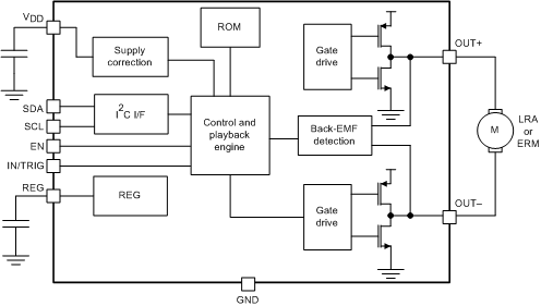
简化原理图
DRV2605L simplifiedSchematic_slos854.gif