ZHCSG01C February   2017  – August 2018 DRV8320 , DRV8320R , DRV8323 , DRV8323R

PRODUCTION DATA.  

  1. 特性
  2. 应用
  3. 说明
    1.     简化原理图
  4. 修订历史记录
  5. Device Comparison Table
  6. Pin Configuration and Functions
    1.     Pin Functions—32-Pin DRV8320 Devices
    2.     Pin Functions—40-Pin DRV8320R Devices
    3.     Pin Functions—40-Pin DRV8323 Devices
    4.     Pin Functions—48-Pin DRV8323R Devices
  7. Specifications
    1. 7.1 Absolute Maximum Ratings
    2. 7.2 ESD Ratings
    3. 7.3 Recommended Operating Conditions
    4. 7.4 Thermal Information
    5. 7.5 Electrical Characteristics
    6. 7.6 SPI Timing Requirements
    7. 7.7 Typical Characteristics
  8. Detailed Description
    1. 8.1 Overview
    2. 8.2 Functional Block Diagram
    3. 8.3 Feature Description
      1. 8.3.1 Three Phase Smart Gate Drivers
        1. 8.3.1.1 PWM Control Modes
          1. 8.3.1.1.1 6x PWM Mode (PWM_MODE = 00b or MODE Pin Tied to AGND)
          2. 8.3.1.1.2 3x PWM Mode (PWM_MODE = 01b or MODE Pin = 47 kΩ to AGND)
          3. 8.3.1.1.3 1x PWM Mode (PWM_MODE = 10b or MODE Pin = Hi-Z)
          4. 8.3.1.1.4 Independent PWM Mode (PWM_MODE = 11b or MODE Pin Tied to DVDD)
        2. 8.3.1.2 Device Interface Modes
          1. 8.3.1.2.1 Serial Peripheral Interface (SPI)
          2. 8.3.1.2.2 Hardware Interface
        3. 8.3.1.3 Gate Driver Voltage Supplies
        4. 8.3.1.4 Smart Gate Drive Architecture
          1. 8.3.1.4.1 IDRIVE: MOSFET Slew-Rate Control
          2. 8.3.1.4.2 TDRIVE: MOSFET Gate Drive Control
          3. 8.3.1.4.3 Propagation Delay
          4. 8.3.1.4.4 MOSFET VDS Monitors
          5. 8.3.1.4.5 VDRAIN Sense Pin
      2. 8.3.2 DVDD Linear Voltage Regulator
      3. 8.3.3 Pin Diagrams
      4. 8.3.4 Low-Side Current Sense Amplifiers (DRV8323 and DRV8323R Only)
        1. 8.3.4.1 Bidirectional Current Sense Operation
        2. 8.3.4.2 Unidirectional Current Sense Operation (SPI only)
        3. 8.3.4.3 Auto Offset Calibration
        4. 8.3.4.4 MOSFET VDS Sense Mode (SPI Only)
      5. 8.3.5 Step-Down Buck Regulator
        1. 8.3.5.1 Fixed Frequency PWM Control
        2. 8.3.5.2 Bootstrap Voltage (CB)
        3. 8.3.5.3 Output Voltage Setting
        4. 8.3.5.4 Enable nSHDN and VIN Undervoltage Lockout
        5. 8.3.5.5 Current Limit
        6. 8.3.5.6 Overvoltage Transient Protection
        7. 8.3.5.7 Thermal Shutdown
      6. 8.3.6 Gate Driver Protective Circuits
        1. 8.3.6.1 VM Supply Undervoltage Lockout (UVLO)
        2. 8.3.6.2 VCP Charge Pump Undervoltage Lockout (CPUV)
        3. 8.3.6.3 MOSFET VDS Overcurrent Protection (VDS_OCP)
          1. 8.3.6.3.1 VDS Latched Shutdown (OCP_MODE = 00b)
          2. 8.3.6.3.2 VDS Automatic Retry (OCP_MODE = 01b)
          3. 8.3.6.3.3 VDS Report Only (OCP_MODE = 10b)
          4. 8.3.6.3.4 VDS Disabled (OCP_MODE = 11b)
        4. 8.3.6.4 VSENSE Overcurrent Protection (SEN_OCP)
          1. 8.3.6.4.1 VSENSE Latched Shutdown (OCP_MODE = 00b)
          2. 8.3.6.4.2 VSENSE Automatic Retry (OCP_MODE = 01b)
          3. 8.3.6.4.3 VSENSE Report Only (OCP_MODE = 10b)
          4. 8.3.6.4.4 VSENSE Disabled (OCP_MODE = 11b or DIS_SEN = 1b)
        5. 8.3.6.5 Gate Driver Fault (GDF)
        6. 8.3.6.6 Thermal Warning (OTW)
        7. 8.3.6.7 Thermal Shutdown (OTSD)
    4. 8.4 Device Functional Modes
      1. 8.4.1 Gate Driver Functional Modes
        1. 8.4.1.1 Sleep Mode
        2. 8.4.1.2 Operating Mode
        3. 8.4.1.3 Fault Reset (CLR_FLT or ENABLE Reset Pulse)
      2. 8.4.2 Buck Regulator Functional Modes
        1. 8.4.2.1 Continuous Conduction Mode (CCM)
        2. 8.4.2.2 Eco-mode Control Scheme
    5. 8.5 Programming
      1. 8.5.1 SPI Communication
        1. 8.5.1.1 SPI
          1. 8.5.1.1.1 SPI Format
    6. 8.6 Register Maps
      1. Table 1. DRV832xS and DRV832xRS Register Map
      2. 8.6.1    Status Registers
        1. 8.6.1.1 Fault Status Register 1 (address = 0x00)
          1. Table 11. Fault Status Register 1 Field Descriptions
        2. 8.6.1.2 Fault Status Register 2 (address = 0x01)
          1. Table 12. Fault Status Register 2 Field Descriptions
      3. 8.6.2    Control Registers
        1. 8.6.2.1 Driver Control Register (address = 0x02)
          1. Table 14. Driver Control Field Descriptions
        2. 8.6.2.2 Gate Drive HS Register (address = 0x03)
          1. Table 15. Gate Drive HS Field Descriptions
        3. 8.6.2.3 Gate Drive LS Register (address = 0x04)
          1. Table 16. Gate Drive LS Register Field Descriptions
        4. 8.6.2.4 OCP Control Register (address = 0x05)
          1. Table 17. OCP Control Field Descriptions
        5. 8.6.2.5 CSA Control Register (DRV8323x Only) (address = 0x06)
          1. Table 18. CSA Control Field Descriptions
  9. Application and Implementation
    1. 9.1 Application Information
    2. 9.2 Typical Application
      1. 9.2.1 Primary Application
        1. 9.2.1.1 Design Requirements
        2. 9.2.1.2 Detailed Design Procedure
          1. 9.2.1.2.1 External MOSFET Support
            1. 9.2.1.2.1.1 Example
          2. 9.2.1.2.2 IDRIVE Configuration
            1. 9.2.1.2.2.1 Example
          3. 9.2.1.2.3 VDS Overcurrent Monitor Configuration
            1. 9.2.1.2.3.1 Example
          4. 9.2.1.2.4 Sense Amplifier Bidirectional Configuration (DRV8323 and DRV8323R)
            1. 9.2.1.2.4.1 Example
          5. 9.2.1.2.5 Buck Regulator Configuration (DRV8320R and DRV8323R)
        3. 9.2.1.3 Application Curves
      2. 9.2.2 Alternative Application
        1. 9.2.2.1 Design Requirements
        2. 9.2.2.2 Detailed Design Procedure
          1. 9.2.2.2.1 Sense Amplifier Unidirectional Configuration
            1. 9.2.2.2.1.1 Example
  10. 10Power Supply Recommendations
    1. 10.1 Bulk Capacitance Sizing
  11. 11Layout
    1. 11.1 Layout Guidelines
      1. 11.1.1 Buck-Regulator Layout Guidelines
    2. 11.2 Layout Example
  12. 12器件和文档支持
    1. 12.1 器件支持
      1. 12.1.1 器件命名规则
    2. 12.2 文档支持
      1. 12.2.1 相关文档
    3. 12.3 相关链接
    4. 12.4 接收文档更新通知
    5. 12.5 社区资源
    6. 12.6 商标
    7. 12.7 静电放电警告
    8. 12.8 术语表
  13. 13机械、封装和可订购信息

封装选项

机械数据 (封装 | 引脚)
散热焊盘机械数据 (封装 | 引脚)
订购信息

说明

DRV832x 系列器件是适用于三相 应用的集成式栅极驱动器。这些器件具有三个半桥栅极驱动器,每个驱动器都能够驱动高侧和低侧 N 沟道功率 MOSFET。DRV832x 使用集成电荷泵为高侧 MOSFET 生成合适的栅极驱动电压,并使用线性稳压器为低侧 MOSFET 生成合适的栅极驱动电压。此智能栅极驱动架构支持高达 1A 的峰值栅极驱动拉电流和 2A 的峰值栅极驱动灌电流。DRV832x 可由单个电源供电,并支持适用于栅极驱动器的 6V 至 60V,以及适用于可选降压稳压器的 4V 至 60V 宽输入电源范围。

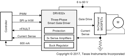
6x、3x、1x 和独立输入 PWM 模式可简化与控制器电路的连接。栅极驱动器和器件的配置设置具有高度可配置性,可通过 SPI 或硬件 (H/W) 接口实现。DRV8323 和 DRV8323R 器件集成了三个低侧电流检测放大器,可在驱动级的全部三个相位上进行双向电流检测。DRV8320R 和 DRV8323R 器件集成了一个 600mA 降压稳压器。

提供了低功耗睡眠模式,以通过关断大部分的内部电路实现较低的静态电流消耗。针对欠压锁定、电荷泵故障、MOSFET 过流、MOSFET 短路、栅极驱动器故障和过热等情况,提供内部保护功能。故障状况及故障详情可通过 SPI 器件型号的器件寄存器显示在 nFAULT 引脚上。

器件信息(1)

器件型号 封装 封装尺寸(标称值)
DRV8320 WQFN (32) 5.00mm × 5.00mm
DRV8320R VQFN (40) 6.00mm × 6.00mm
DRV8323 WQFN (40) 6.00mm × 6.00mm
DRV8323R VQFN (48) 7.00mm × 7.00mm
  1. 如需了解所有可用封装,请参阅数据表末尾的可订购米6体育平台手机版_好二三四附录。

简化原理图
DRV8320 DRV8320R DRV8323 DRV8323R simp_sch_slvsdj3.gif