ZHCSWR1H December 2009 – July 2024 DRV8412
PRODUCTION DATA
- 1
- 1特性
- 2应用
- 3说明
- 4Pin Configuration and Functions
- 5Specifications
- 6Detailed Description
-
Application and Implementation
- 7.1 Application Information
- 7.2 Typical Applications
- 7.3 Power Supply Recommendations
- 7.4 Layout
- 7Device and Documentation Support
- 8Revision History
- 9Mechanical, Packaging, and Orderable Information
7.4.3.1 DRV8412 Thermal Via Design Recommendation
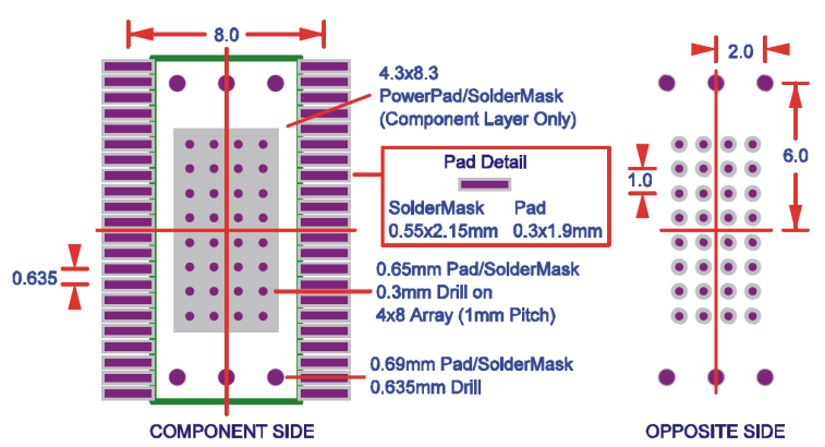
Thermal pad of the DRV8412 is attached at bottom of device to improve the thermal capability of the device. The thermal pad has to be soldered with a very good coverage on PCB to deliver the power specified in the data sheet. Figure 7-16 shows the recommended thermal via and land pattern design for the DRV8412. For additional information, see TI application report, PowerPad™ Made Easy (SLMA004) and PowerPad Layout Guidelines (SOLA120).
 Figure 7-16 DRV8412 Thermal Via Footprint