SLOSEC6 August 2024 DRV8434A-Q1
PRODUCTION DATA
- 1
- 1 Features
- 2 Applications
- 3 Description
- 4 Pin Configuration and Functions
- 5 Specifications
-
6 Detailed Description
- 6.1 Overview
- 6.2 Functional Block Diagram
- 6.3
Feature Description
- 6.3.1 Stepper Motor Driver Current Ratings
- 6.3.2 PWM Motor Drivers
- 6.3.3 Microstepping Indexer
- 6.3.4 Controlling VREF with an MCU DAC
- 6.3.5 Current Regulation and Decay Mode
- 6.3.6 Charge Pump
- 6.3.7 Linear Voltage Regulators
- 6.3.8 Logic Level, Tri-Level and Quad-Level Pin Diagrams
- 6.3.9 Protection Circuits
- 6.4 Device Functional Modes
- 7 Application and Implementation
- 8 Power Supply Recommendations
- 9 Layout
- 10Device and Documentation Support
- 11Revision History
- 12Mechanical, Packaging, and Orderable Information
6.3.9.4 Stall Detection
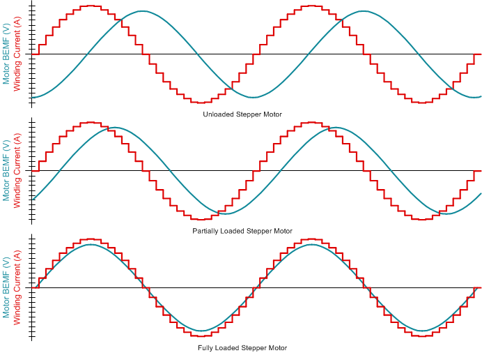
Stepper motors have a distinct relation between the winding current, back-EMF, and mechanical torque load of the motor, as shown in Figure 6-13. As motor load approaches the torque capability of the motor for a given winding current, the back-EMF will move in phase with the winding current.
By detecting back-emf phase shift between rising and falling current quadrants of the motor current, the DRV8434A-Q1 can detect a motor overload stall condition or an end-of-line travel. Without Stall Detection, driver will continue to drive through the obstacle, causing heating, audible noise and damage to the system.
Stall detection can replace expensive Hall sensors. Integrated sensorless stall detection results in immediate response in the event of motor stall, compared to timeout mechanism of Hall sensors.
 Figure 6-13 Stall Detection by Monitoring Motor Back-EMF
The stall detection algorithm compares the back-EMF between the rising and falling current quadrants by monitoring PWM off time and generates a value represented by the torque count. The comparison is done in such a way that the torque count is practically independent of motor current, ambient temperature and supply voltage.
For a lightly loaded motor, the torque count will be a non-zero value. As the motor approaches stall condition, torque count will approach zero and can be used to detect stall condition. If anytime torque count falls below the stall threshold, the device will detect a stall. In stalled condition, the motor shaft does not spin. The motor starts to spin again when the stall condition is removed.
High motor coil resistance can result in low torque count. The ENABLE pin of the DRV8434A-Q1 allows scaling up low torque count values, for ease of further processing. If the ENABLE pin is Hi-Z, the torque count and stall threshold are multiplied by a factor of 8. If the ENABLE pin is logic high, torque count and stall threshold retain the value originally calculated by the algorithm.
The stall detection algorithm of the DRV8434A-Q1 is configured by two digital IO and one analog IO pins - STL_MODE, STL_REP and TRQ_CNT/STL_TH.
STL_MODE programs the stall detection mode. When this pin is logic low, stall threshold is computed by the driver or an external microcontroller (MCU). The TRQ_CNT/STL_TH pin outputs as torque count analog voltage. If the STL_MODE pin is open (Hi-Z), it enables the stall threshold learning process. If learning is successful, the TRQ_CNT/STL_TH pin outputs the stall threshold as an analog voltage. When the STL_MODE is logic high (tied to DVDD), stall threshold is set by applying a voltage on the TRQ_CNT/STL_TH pin. TRQ_CNT/STL_TH pin can act as both input or output, depending on the operating mode. An 1 nF capacitor must be connected from the TRQ_CNT/STL_TH pin to GND. Connecting a 330k resistor from STL_MODE pin to ground disables stall detection. Additionally, if any fault condition exists (UVLO, OCP, OL, OTSD etc.), stall detection will be disabled.
STL_REP is an open-drain output. When STL_MODE = GND or DVDD, STL_REP is pulled low by the driver if there is no stall fault; and goes high if stall is detected. If STL_MODE = GND or DVDD and the STL_REP pin is pulled low externally, then stall fault reporting is disabled and nFAULT will not go low if a stall is detected. In stall threshold learning mode (STL_MODE = Hi-Z), if STL_REP goes from high to low, it indicates successful stall threshold learning. STL_REP must be pulled up with an external pull-up resistor.
The following procedure describes the stall threshold learning operation:
- Before stall threshold learning, ensure that the motor speed has reached its target value. Do not learn stall threshold while the motor speed is ramping up or down.
- Initiate learning by making the STL_MODE pin Hi-Z.
- Run motor with no load.
- Wait for 32 electrical cycles for the driver to learn the steady count.
- Stall the motor.
- Wait for 16 electrical cycles for the driver to learn the stall count.
- STL_REP will be pulled low if learning is successful.
- Stall threshold is calculated as the average of steady count and stall count.
- At the end of a successful learning, TRQ_CNT/STL_TH pin outputs the stall threshold as an analog voltage, and also stores the value internally for use with Torque Count Mode.
- After successful learning, once device enters Torque Count mode or Stall Threshold mode by changing STL_MODE logic level, STL_REP goes high, nFAULT is pulled down and the voltage on the TRQ_CNT/STL_TH pin is reset.
- Apply nSLEEP reset pulse to pull down STL_REP and pull up nFAULT again.
Sometimes the stall learning process might not be successful due to an unstable torque count while the motor is running or stalled. For example, when the motor has high coil resistance or is running at very high or low speeds, the torque count might vary a lot over time and the difference between steady count and stall count might be small. In such cases, it is recommended not to use the stall learning method. Instead, the user should carefully study the steady count and torque count across the range of operating conditions and set the threshold midway between the minimum steady count and the maximum stall count.
When the motor is intially ramping up speed, it is recommended to configure the driver in either Torque Count Mode or Stall Threshold Mode. If the device is in Learning Mode during the initial ramp up, the learning process might result in a lower stall threshold value. Once steady state speed has been achieved, learning process can be initiated.
Table 6-6 shows all the different operating modes in which stall can be detected.
| Operating Mode | STL_MODE | TRQ_CNT/STL_TH | STL_REP | nFAULT | Description |
|---|---|---|---|---|---|
| Torque Count Mode | GND | Torque count voltage as output | Output:High: Stall Fault Input:Low: Stall Reporting Disabled | If STL_REP > 1.6V, nFAULT goes low when stall is detected | This Mode supports two types of operations: 1. Standalone Stall Detection Mode: Driver takes care of stall detection and reporting (this needs to be preceded by Learning Mode). 2. MCU assisted Stall Detection Mode: MCU takes TRQ_CNT/STL_TH voltage as input, compensates it for any second order effects, and compares it with its own stall threshold value to detect a stall. Because this operating mode is external, the device stall reporting must be disabled. The MCU could also run an algorithm to control VREF based on the torque count. |
| Learning Mode | Hi-Z | Stall threshold voltage as output | Output:High: Learning Not done Low: learning Successful | Not Applicable | 1. Torque count learning result is available via the TRQ_CNT/STL_TH pin. 2. In this mode, the motor must spin with no load for at least 32 electrical cycles, then stalled for at least 16 electrical cycles for the stall detection algorithm to determine the internal stall threshold. |
| Stall Threshold Mode | DVDD | Stall threshold voltage as input | Output:High: Stall Fault Input:Low: Stall Reporting Disabled | If STL_REP > 1.6V, nFAULT goes low when stall is detected | Torque count is noted from Torque Count Mode or Learning Mode and a desired stall threshold voltage is applied to the TRQ_CNT/STL_TH pin. The stall threshold voltage must be less than the torque count noted from the Torque Count Mode. Stall Threshold Mode must be selected while the motor is spinning in Torque Count Mode. |
Stall Detection Disabled | 330k to GND | Output: Low | Motor stall will be ignored until STL_MODE = 0 or 1. |
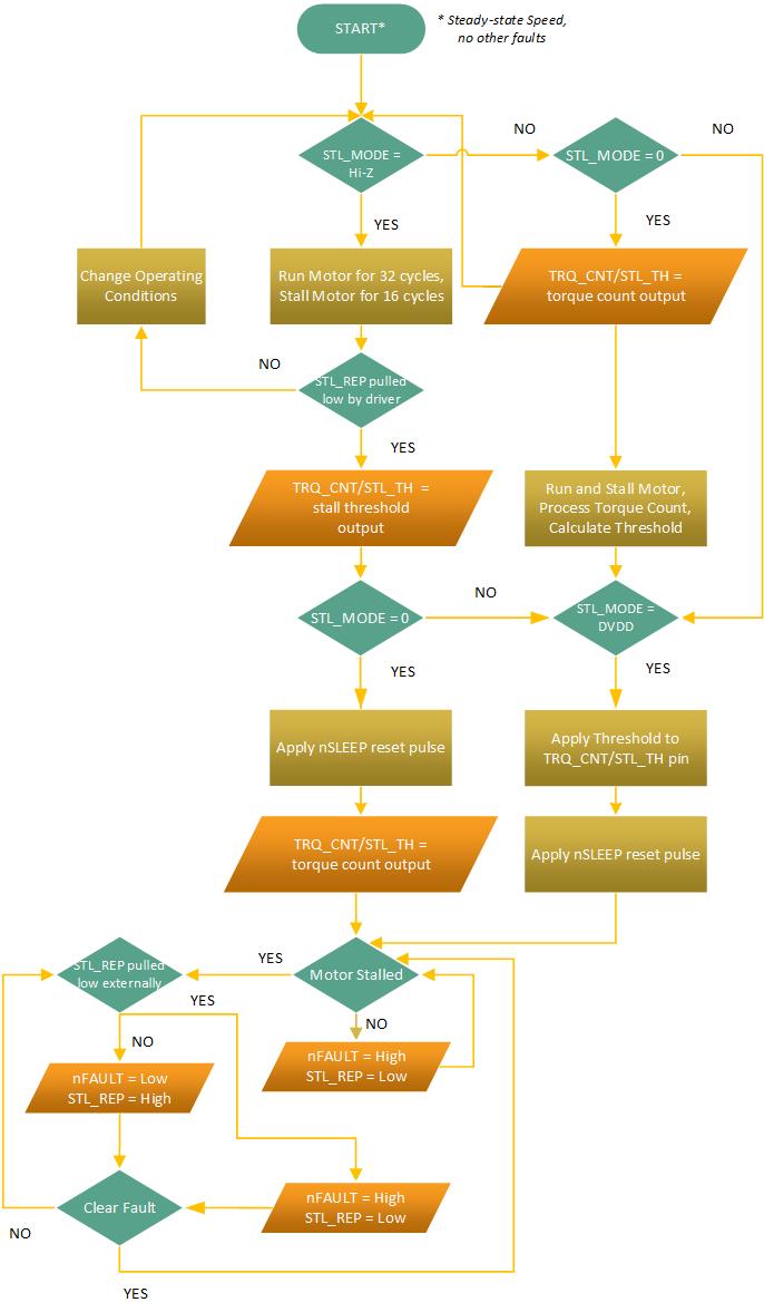
Figure 6-14 shows the flowchart of stall detection by the DRV8434A-Q1 driver.
 Figure 6-14 Flowchart of Stall Detection by DRV8434A-Q1