ZHCSCV7 August 2014 DRV8833C
PRODUCTION DATA.
- 1 特性
- 2 应用
- 3 说明
- 4 修订历史记录
- 5 Pin Configuration and Functions
- 6 Specifications
- 7 Detailed Description
- 8 Application and Implementation
- 9 Power Supply Recommendations
- 10Layout
- 11器件和文档支持
- 12机械封装和可订购信息
封装选项
机械数据 (封装 | 引脚)
散热焊盘机械数据 (封装 | 引脚)
- RTE|16
订购信息
8 Application and Implementation
8.1 Application Information
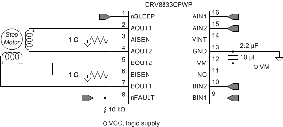
The DRV8833C is used in stepper or brushed DC motor control. The following design procedure can be used to configure the DRV8833C in a bipolar stepper motor application.
8.2 Typical Application

8.2.1 Design Requirements
Table 5 gives design input parameters for system design.
Table 5. Design Parameters
| Design Parameter | Reference | Example Value |
|---|---|---|
| Supply voltage | VM | 9 V |
| Motor winding resistance | RL | 12 Ω/phase |
| Motor winding inductance | LL | 10 mH/phase |
| Motor full step angle | θstep | 1.8 °/step |
| Target stepping level | nm | 2 (half-stepping) |
| Target motor speed | v | 120 rpm |
| Target chopping current | ICHOP | 200 mA |
| Sense resistor | RISEN | 1 Ω |
8.2.2 Detailed Design Procedure
8.2.2.1 Stepper Motor Speed
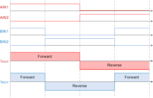
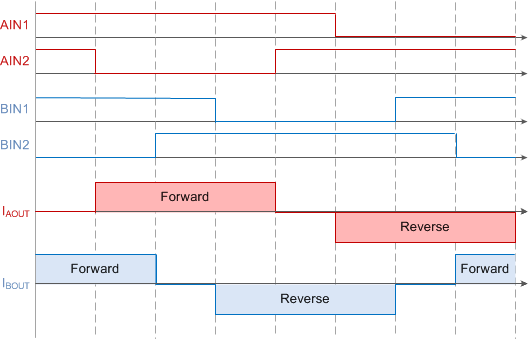
The first step in configuring the DRV8833C requires the desired motor speed and stepping level. The DRV8833C can support full- and half-stepping modes using the PWM interface.
If the target motor speed is too high, the motor does not spin. Ensure that the motor can support the target speed.
For a desired motor speed (v), microstepping level (nm), and motor full step angle (θstep),

 Figure 10. Full-Step Mode
 Figure 11. Half-Step Mode
8.2.2.2 Current Regulation
The chopping current (ICHOP) is the maximum current driven through either winding. This quantity depends on the sense resistor value (RXISEN).

ICHOP is set by a comparator which compares the voltage across RXISEN to a reference voltage. Note that ICHOP must follow Equation 4 to avoid saturating the motor.

where
- VM is the motor supply voltage.
- RL is the motor winding resistance.
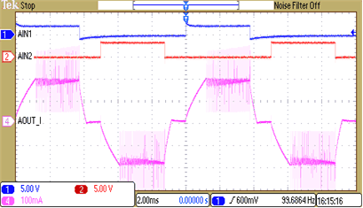
8.2.3 Application Curve
