SLVSET1 August 2018 DRV8873
PRODUCTION DATA.
- 1 Features
- 2 Applications
- 3 Description
- 4 Revision History
- 5 Pin Configuration and Functions
- 6 Specifications
-
7 Detailed Description
- 7.1 Overview
- 7.2 Functional Block Diagram
- 7.3 Feature Description
- 7.4 Device Functional Modes
- 7.5 Programming
- 7.6 Register Maps
- 8 Application and Implementation
- 9 Power Supply Recommendations
- 10Layout
- 11Device and Documentation Support
- 12Mechanical, Packaging, and Orderable Information
7.3.1.8 nSLEEP as SDO Reference
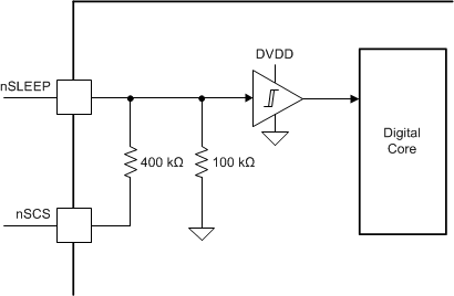
The nSLEEP pin manages the state of the device. The device goes into sleep mode with a logic-low signal, and comes out of sleep mode when the nSLEEP pin goes high. The signal level when the nSLEEP pin goes high determines the logic level on the SDO output in the SPI version of the device. A 3.3-V signal on the nSLEEP pin provides a 3.3-V output on the SDO output. A 5-V signal on the nSLEEP pin provides a 5-V output on the SDO pin. If the sleep feature is not required, the nSLEEP pin can be connected to the MCU power supply. In that case, when the MCU is powered-up, the motor driver device is also be powered-up.
 Figure 18. nSCS and nSLEEP Circuit
 In the SPI version of the device, if the nSLEEP reset pulse is used to clear faults, the SDO voltage reference is not available for the duration of the nSLEEP reset pulse. No data can be transmitted on the SDO line for the duration when the nSLEEP pin is held low. Therefore, TI recommends using the CLR_FLT bit in the IC3 control register to clear the faults.