SNLS348E October 2011 – January 2015 DS100BR210
PRODUCTION DATA.
- 1 Features
- 2 Applications
- 3 Description
- 4 Simplified Schematic
- 5 Revision History
- 6 Pin Configuration and Functions
- 7 Specifications
- 8 Detailed Description
- 9 Application and Implementation
- 10Power Supply Recommendations
- 11Layout
- 12Device and Documentation Support
- 13Mechanical, Packaging, and Orderable Information
9 Application and Implementation
NOTE
Information in the following applications sections is not part of the TI component specification, and TI does not warrant its accuracy or completeness. TI’s customers are responsible for determining suitability of components for their purposes. Customers should validate and test their design implementation to confirm system functionality.
9.1 Application Information
9.1.1 Signal Integrity in 10G-KR Applications
When configured in "KR Mode", using either the VOD_SEL and MODE pin setting or SMBus register control, the DS100BR210 is designed to operate transparently within a KR backplane channel environment. Installing a DS100BR210 repeater within the KR backplane channel splits the total channel attenuation into two parts. In other words, operating in "KR Mode" implies that signals will pass through the repeater with a linearized output. Ideally the repeater can be placed near the middle of the channel, maximizing the signal-to-noise ratio across the bidirectional interface.
In order to maximize the 10G-KR solution space, the 802.3ap specification calls for an optimization of the Tx partner signal conditioning coefficients based on feedback from the KR Rx ASIC endpoint. This link optimization sequence is commonly referred to as "link training" and is performed at speed (10.3125 Gbps). Setting the DS100BR210 active CTLE to compensate for the channel loss from each of the KR transmitters will reduce the transmit and receive equalization settings required on the KR physical layer devices. This central location keeps a larger signal-to-noise ratio at all points in the channel, extending the available solution space and increasing the overall margin of almost any channel. Suggested initial settings for the DS100BR210 are given in Table 10 and Table 11. Further adjustments to EQx, DEMx, and VODx settings may optimize signal margin on the link for different system applications.
Table 10. Suggested 10G-KR Initial Device Settings in Pin Mode(1)
| CHANNEL SETTINGS | PIN MODE |
|---|---|
| EQx[1:0] | 0, 0 |
| VOD_SEL | 1 |
| DEMx | 0 |
Table 11. Suggested 10G-KR Initial Device Settings in SMBus Modes
| CHANNEL SETTINGS | SMBus MODES |
|---|---|
| EQx | 0x00 |
| VODx | 100'b |
| DEMx | 000'b |
The SMBus Slave Mode code example in Table 12 may be used to program the DS100BR210 with the recommended device settings.
Table 12. SMBus 10G-KR Example Sequence
| REGISTER | WRITE VALUE | COMMENTS | ||
|---|---|---|---|---|
| 0x06 | 0x18 | Set SMBus Slave Mode Register Enable. | ||
| 0x08 | 0x04 | Enable Output Mode Control for individual channel outputs. | ||
| 0x0F | 0x00 | Set CHA EQ to 0x00. | ||
| 0x10 | 0xAD | Set CHA Output Mode to Linear (10G-KR mode). If link-training is not required, set Reg 0x10 to 0xED. |
||
| 0x11 | 0x00 | Set CHA DEM to 000'b. | ||
| 0x16 | 0x00 | Set CHB EQ to 0x00. | ||
| 0x17 | 0xAD | Set CHB Output Mode to Linear (10G-KR mode). If link-training is not required, set Reg 0x18 to 0xED. |
||
| 0x18 | 0x00 | Set CHB DEM to 000'b. | ||
| 0x25 | 0xB1 | Set CHA VOD to 100'b. | ||
| 0x28 | 0x00 | Leave Idle Control at default levels. For SAS/SATA applications, set Reg 0x28 to 0x4C. |
||
| 0x2D | 0xB1 | Set CHB VOD to 100'b. | ||
9.1.2 OOB (Out-of-Band) Functionality in SAS/SATA Applications
For SAS/SATA systems, a low speed OOB (Out-of-Band) communication sequence is used to detect and communicate device capabilities between host ASIC and link partners. These OOB signals, including COMWAKE, COMINIT, COMRESET, and COMSAS, are a series of burst, idle, and negation times transmitted and detected across the SAS/SATA link. These bursts occur at a rapid rate, with the COMWAKE signal having the most stringent requirement of 106.6 ns active followed by 106.6 ns idle. Normally, if the device is set in 10G-KR mode (MODE pin floating), the device goes idle-to-active in approximately 150 ns. If the device is set to SAS mode (MODE pin tied via 1 kΩ to VDD (2.5 V mode) or VIN (3.3 V mode)), the device goes idle-to-active in approximately 3 to 4 ns. This fast idle-to-active time is critical to pass OOB signaling, and when operating in pin mode, the MODE pin should be tied high. If operating in SMBus slave mode, the user can set Reg 0x28 to 0x4C for this faster idle-to-active response.
9.2 Typical Application
The DS100BR210 works to extend the reach possible by using active equalization on the channel, boosting attenuated signals so that they can be more easily recovered at the Rx endpoint. The capability of the repeater can be explored across a range of data rates and ASIC-to-link-partner signaling, as shown in the following test setup connections. The test setup connections diagrams shown represent typical generic application scenarios for the DS100BR210.
 Figure 10. Test Setup Connections Diagram
Pre-Channel Only
 Figure 11. Test Setup Connections Diagram
Pre-Channel and Post-Channel, No Tx Source De-emphasis
 Figure 12. Test Setup Connections Diagram
Pre-Channel and Post-Channel, -6 dB Tx Source De-emphasis
9.2.1 Design Requirements
As with any high speed design, there are many factors that influence the overall performance. Below are a list of critical areas for consideration during design.
- Use 100 Ω impedance traces. Length matching on the P and N traces should be done on the single-ended segments of the differential pair.
- Use uniform trace width and trace spacing for differential pairs.
- Place AC-coupling capacitors near to the receiver end of each channel segment to minimize reflections.
- The maximum body size for AC-coupling capacitors is 0402.
- Back-drill connector vias and signal vias to minimize stub length.
- Use Reference plane vias to ensure a low inductance path for the return current.
9.2.2 Detailed Design Procedure
The DS100BR210 is designed to be placed at an offset location with respect to the overall channel attenuation. In order to optimize performance, the repeater requires optimization to extend the reach of the cable or trace length while also recovering a solid eye opening. To optimize the repeater in a 10G-KR environment, the settings mentioned in Table 10 (for Pin Mode) and Table 11 (for SMBus Modes) are recommended as a default starting point. For a generic 10GbE application where link training is not required, the following settings in Table 13 and Table 14 may be referenced as an initial starting point:
Table 13. Suggested Generic 10GbE Initial Device Settings in Pin Mode(1)
| CHANNEL SETTINGS | PIN MODE |
|---|---|
| EQx[1:0] | 0, 0 |
| VOD_SEL | 0 |
| DEMx | 0 |
Table 14. Suggested Generic 10GbE Initial Device Settings in SMBus Modes
| CHANNEL SETTINGS | SMBus MODES |
|---|---|
| EQx | 0x00 |
| VODx | 000'b |
| DEMx | 000'b |
Examples of the repeater performance are illustrated in the performance curves in the next section.
9.2.3 Application Performance Plots
The lab setups referenced in Figure 10 to Figure 12 were used to collect typical performance data on FR4 and cable media. For all measurements, Mode Pin = Float.
9.2.3.1 Equalization Results (Pre-Channel Only)
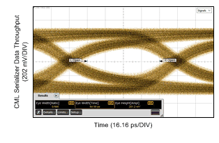
No Repeater, 8 Gbps
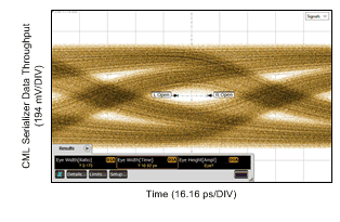
No Repeater, 10.3125 Gbps
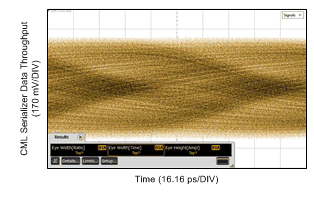
No Repeater, 10.3125 Gbps
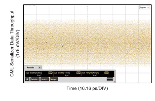
No Repeater, 10.3125 Gbps
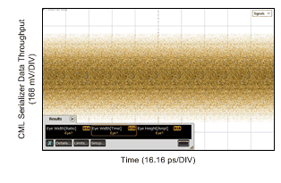
No Repeater Used, 10.3125 Gbps
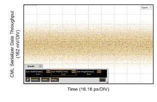
No Repeater Used, 10.3125 Gbps
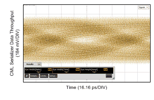
No Repeater, 10.3125 Gbps
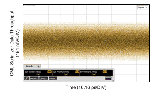
No Repeater, 10.3125 Gbps
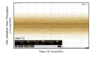
No Repeater, 10.3125 Gbps
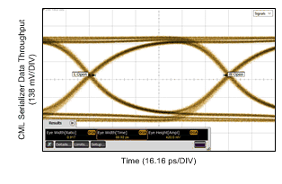
DS100BR210 CHA, 10.3125 Gbps
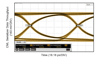
DS100BR210 CHA, 10.3125 Gbps
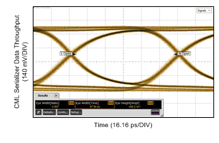
DS100BR210 CHA, 10.3125 Gbps
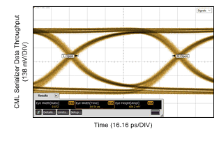
DS100BR210 CHA, 10.3125 Gbps
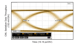
DS100BR210 CHA, 10.3125 Gbps
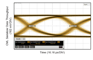
DS100BR210 CHA, 10.3125 Gbps
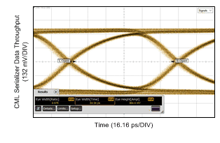
DS100BR210 CHA, 10.3125 Gbps
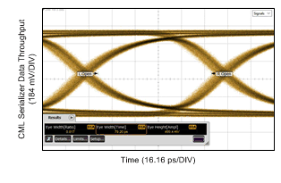
DS100BR210 CHA, 10.3125 Gbps
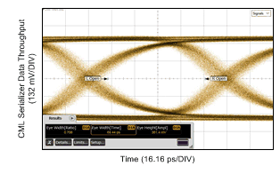
DS100BR210 CHA, 10.3125 Gbps
9.2.3.2 Equalization and De-Emphasis Results
(Pre-channel and Post-channel, No Tx Source De-emphasis)
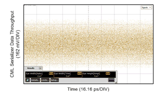
TL2 = 10 Inch 4–Mil FR4 Trace,
No Repeater, 10.3125 Gbps
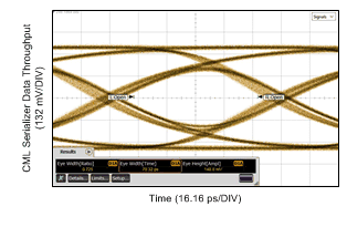
TL2 = 10 Inch 4–Mil FR4 Trace,
DS100BR210 CHA, 10.3125 Gbps
9.2.3.3 Equalization and De-Emphasis Results
(Pre-channel and Post-channel, -6 dB Tx Source De-emphasis)
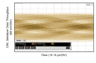
TL2 = 10 Inch 4–Mil FR4 Trace,
No Repeater, 10.3125 Gbps
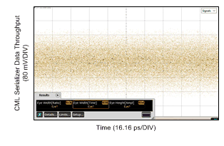
TL2 = 10 Inch 4–Mil FR4 Trace,
No Repeater, 10.3125 Gbps
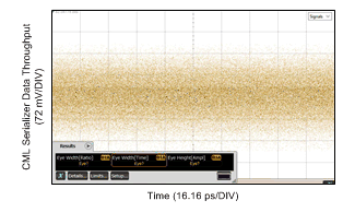
TL2 = 10 Inch 4–Mil FR4 Trace,
No Repeater, 10.3125 Gbps
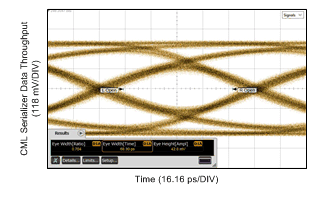
TL2 = 10 Inch 4–Mil FR4 Trace,
DS100BR210 CHA, 10.3125 Gbps
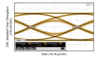
TL2 = 10 Inch 4–Mil FR4 Trace,
DS100BR210 CHA, 10.3125 Gbps
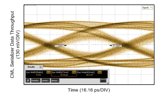
TL2 = 10 Inch 4–Mil FR4 Trace,
DS100BR210 CHA, 10.3125 Gbps