ZHCSDR9D July   2012  – May 2015 DS125BR401

PRODUCTION DATA.  

  1. 特性
  2. 应用范围
  3. 说明
  4. 典型应用
  5. 修订历史记录
  6. 说明(续)
  7. Pin Configuration and Functions
  8. Specifications
    1. 8.1 Absolute Maximum Ratings
    2. 8.2 ESD Ratings
    3. 8.3 Recommended Operating Conditions
    4. 8.4 Thermal Information
    5. 8.5 Electrical Characteristics
    6. 8.6 Electrical Characteristics — Serial Management Bus Interface
    7. 8.7 Typical Characteristics
  9. Detailed Description
    1. 9.1 Overview
    2. 9.2 Functional Block Diagram
    3. 9.3 Feature Description
      1. 9.3.1 Typical 4-Level Input Thresholds
    4. 9.4 Device Functional Modes
      1. 9.4.1 Pin Control Mode
      2. 9.4.2 SMBUS Mode
    5. 9.5 Programming
      1. 9.5.1 PCIe Signal Integrity
        1. 9.5.1.1 RX-Detect in SAS/SATA (up to 6 Gbps) Applications
          1. 9.5.1.1.1 Signal Detect Control for Datarates Above 8 Gbps
        2. 9.5.1.2 MODE Operation With SMBus Registers
      2. 9.5.2 SMBUS Master Mode
      3. 9.5.3 System Management Bus (SMBus) and Configuration Registers
        1. 9.5.3.1 Transfer of Data Through the SMBus
        2. 9.5.3.2 SMBus Transactions
        3. 9.5.3.3 Writing a Register
        4. 9.5.3.4 Reading a Register
    6. 9.6 Register Maps
  10. 10Application and Implementation
    1. 10.1 Application Information
    2. 10.2 Typical Application
      1. 10.2.1 Design Requirements
      2. 10.2.2 Detailed Design Procedure
      3. 10.2.3 Application Curves
  11. 11Power Supply Recommendations
    1. 11.1 3.3-V or 2.5-V Supply Mode Operation
    2. 11.2 Power Supply Bypassing
  12. 12Layout
    1. 12.1 Layout Guidelines
      1. 12.1.1 PCB Layout Considerations for Differential Pairs
    2. 12.2 Layout Example
  13. 13器件和文档支持
    1. 13.1 文档支持
      1. 13.1.1 相关文档
    2. 13.2 Community Resources
    3. 13.3 商标
    4. 13.4 静电放电警告
    5. 13.5 术语表
  14. 14机械、封装和可订购信息

封装选项

机械数据 (封装 | 引脚)
散热焊盘机械数据 (封装 | 引脚)
订购信息

10 Application and Implementation

NOTE

Information in the following applications sections is not part of the TI component specification, and TI does not warrant its accuracy or completeness. TI’s customers are responsible for determining suitability of components for their purposes. Customers should validate and test their design implementation to confirm system functionality.

10.1 Application Information

The DS125BR401 is a high performance circuit capable of delivering excellent performance. Careful attention must be paid to the details associated with high-speed design as well as providing a clean power supply. Refer to the following information and Revision 4 of the LVDS Owner's Manual for more detailed information on high-speed design tips to address signal integrity design issues.

10.2 Typical Application

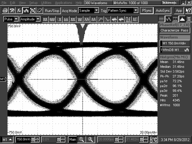
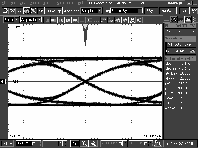
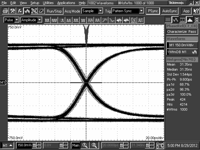
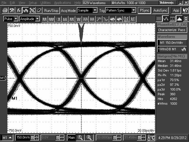
The DS125BR401 works to extend the reach possible by using active equalization on the channel, boosting attenuated signals so that they can be more easily recovered at the Rx endpoint. The capability of the repeater can be explored across a range of data rates and ASIC-to-link-partner signaling, as shown in the following test setup connections. The test setup connections diagrams shown represent typical generic application scenarios for the DS125BR401.

DS125BR401 30198730.gifFigure 9. Test Setup Connections Diagram
DS125BR401 30198733.gifFigure 10. Test Setup Connections Diagram

10.2.1 Design Requirements

As with any high speed design, there are many factors which influence the overall performance. Below are a list of critical areas for consideration and study during design.

  • Use 100-Ω impedance traces. Generally these are very loosely coupled to ease routing length differences.
  • Place AC-coupling capacitors near to the receiver end of each channel segment to minimize reflections.
  • The maximum body size for AC-coupling capacitors is 0402.
  • Back-drill connector vias and signal vias to minimize stub length.
  • Use Reference plane vias to ensure a low inductance path for the return current.

10.2.2 Detailed Design Procedure

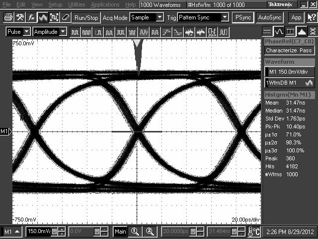
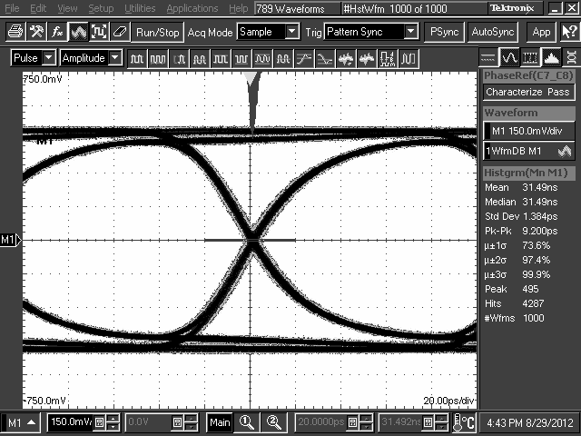
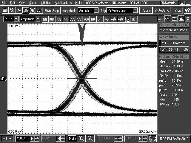
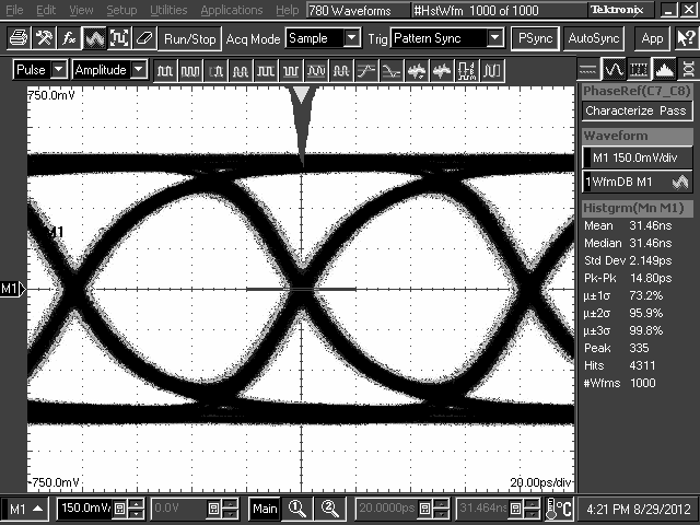
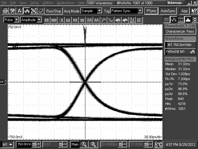
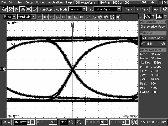
The DS125BR401 is designed to be placed at a location where the input CTLE can help to compensate for a portion of the overall channel attenuation. In order to optimize performance, the repeater requires tuning to extend the reach of the cable or trace length while also recovering a solid eye opening. To tune the repeater, TI recommends the settings mentioned in Table 2 and Table 3 (for Pin Mode) as a default starting point for most applications. Once these settings are configured, additional tuning of the EQ and, to a lesser extent, VOD may be required to optimize the repeater performance for each specific application environment. Examples of the repeater performance as a generic high-speed datapath repeater are illustrated in the performance curves in the next section.

10.2.3 Application Curves
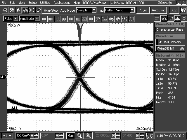
DS125BR401 30198769.png
DS125BR401 settings: EQ[1:0] = 0, F = 0x02, DEM[1:0] = 0, 1
Figure 11. TL = 10-Inch 5-Mil FR4 Trace, 5 Gbps
DS125BR401 30198758.png
DS125BR401 settings: EQ[1:0] = 0, R = 0x01, DEM[1:0] = 0, 1
Figure 13. TL = 10-Inch 5-Mil FR4 Trace, 12 Gbps
DS125BR401 30198761.png
DS125BR401 settings: EQ[1:0] = 0, 1 = 0x03, DEM[1:0] = 0, 1
Figure 15. TL = 20-Inch 5-Mil FR4 Trace, 8 Gbps
DS125BR401 30198766.png
DS125BR401 settings: EQ[1:0] = R, 0 = 0x07, DEM[1:0] = 0, 1
Figure 17. TL = 30-Inch 5-Mil FR4 Trace, 5 Gbps
DS125BR401 30198768.png
DS125BR401 settings: EQ[1:0] = R, 0 = 0x07, DEM[1:0] = 0, 1
Figure 19. TL = 30-Inch 5-Mil FR4 Trace, 12 Gbps
DS125BR401 30198757.png
DS125BR401 settings: EQ[1:0] = R, 1 = 0x0F, DEM[1:0] = 0, 1
Figure 21. TL1 = 8-Meter 30-AWG 100-Ω Twin-Axial Cable, 12 Gbps
DS125BR401 30198763.png
DS125BR401 settings: EQ[1:0] = R, 1 = 0x0F, DEM[1:0] = R, 0
Figure 23. TL1 = 20-Inch 5-Mil FR4 Trace,
TL2 = 10-Inch 5-Mil FR4 Trace, 8 Gbps
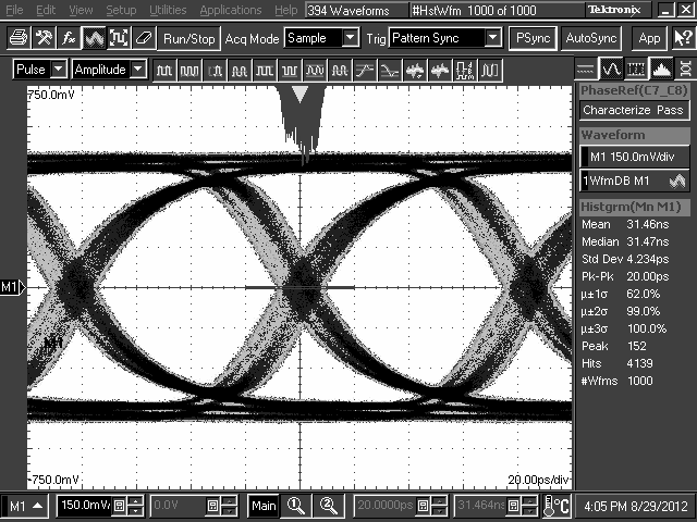
DS125BR401 30198759.png
DS125BR401 settings: EQ[1:0] = 0, F = 0x02, DEM[1:0] = 0, 1
Figure 12. TL = 10-Inch 5-Mil FR4 Trace, 8 Gbps
DS125BR401 30198760.png
DS125BR401 settings: EQ[1:0] = 0, 1 = 0x03, DEM[1:0] = 0, 1
Figure 14. TL = 20-Inch 5-Mil FR4 Trace, 5 Gbps
DS125BR401 30198765.png
DS125BR401 settings: EQ[1:0] = 0, 1 = 0x03, DEM[1:0] = 0, 1
Figure 16. TL = 20-Inch 5-Mil FR4 Trace, 12 Gbps
DS125BR401 30198767.png
DS125BR401 settings: EQ[1:0] = R, 0 = 0x07, DEM[1:0] = 0, 1
Figure 18. TL = 30-Inch 5-Mil FR4 Trace, 8 Gbps
DS125BR401 30198756.png
DS125BR401 settings: EQ[1:0] = R, 0 = 0x07, DEM[1:0] = 0, 1
Figure 20. TL1 = 5-Meter 30-AWG 100-Ω Twin-Axial Cable, 12 Gbps
DS125BR401 30198762.png
DS125BR401 settings: EQ[1:0] = 0, 1 = 0x03, DEM[1:0] = R, 0
Figure 22. TL1 = 20-Inch 5-Mil FR4 Trace,
TL2 = 10-Inch 5-Mil FR4 Trace, 5 Gbps
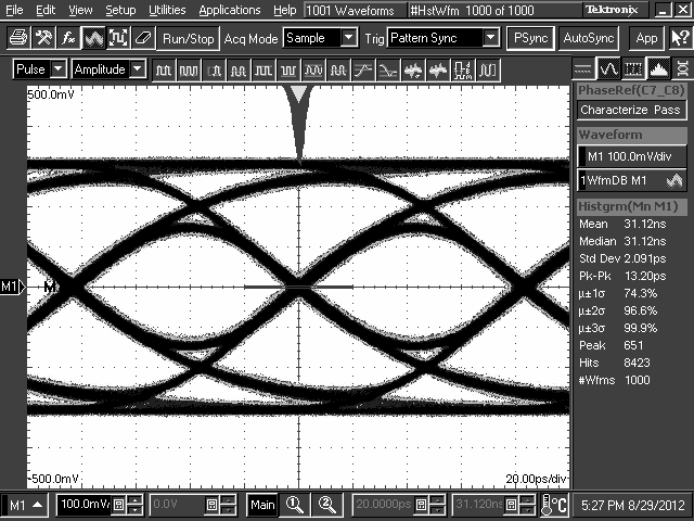
DS125BR401 30198764.png
DS125BR401 settings: EQ[1:0] = R, 1 = 0x0F, DEM[1:0] = R, 0
Figure 24. TL1 = 20-Inch 5-Mil FR4 Trace, TL2 = 10-Inch 5-Mil FR4 Trace, 12 Gbps