ZHCSKE4C october 2016 – december 2020 DS280MB810
PRODUCTION DATA
- 1
- 1 特性
- 2 应用
- 3 说明
- 4 Revision History
- 5 Description (continued)
- 6 Pin Configuration and Functions
- 7 Specifications
- 8 Detailed Description
- 9 Application and Implementation
- 10Power Supply Recommendations
- 11Layout
- 12Device and Documentation Support
- 13Mechanical, Packaging, and Orderable Information
8.4.2 SMBus Master Mode Configuration (EEPROM Self Load)
To configure the DS280MB810 for SMBus master mode, leave the EN_SMB pin floating (no connect). If the DS280MB810 is configured for SMBus master mode, it will remain in the SMBus IDLE state until the READ_EN_N pin is asserted to LOW, or VIL. Once the READ_EN_N pin is driven LOW, the DS280MB810 becomes an SMBus master and attempts to self-configure by reading device settings stored in an external EEPROM (SMBus 8-bit address 0xA0). When the DS280MB810 has finished reading from the EEPROM successfully, it will drive the ALL_DONE_N pin LOW and then change from an SMBus master to an SMBus slave. Not all bits in the register map can be configured through an EEPROM load. Refer to the DS280MB810 Programming Guide for more information.
When designing a system for using the external EEPROM, the user must follow these guidelines:
- Maximum EEPROM size is 8 kb (1024 x 8-bit).
- Set EN_SMB = FLOAT to configure for SMBus master mode.
- The external EEPROM 8-bit device address must be 0xA0 and capable of 400 kHz operation at 2.5 V or 3.3 V supply.
- Once the DS280MB810 completes its EEPROM load the device becomes an SMBus slave on the control bus.
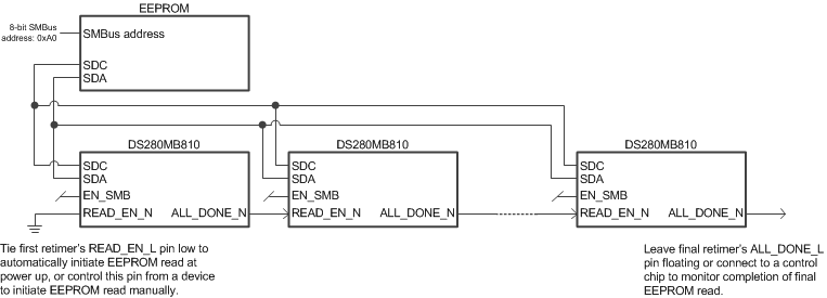
- If multiple DS280MB810 devices share a single EEPROM, connect the ALL_DONE_N output of the first device to the READ_EN_N input of the next device, as shown in Figure 8-4.
 Figure 8-4 Example daisy chain for multiple device, single EEPROM configuration
When tying multiple DS280MB810 devices to the SDA and SDC bus, use these guidelines to configure the devices for SMBus master mode:
- Use SMBus ADDR[1:0] address bits so that each device can load its configuration from the EEPROM. The example below is for four devices. The first device in the sequence conventionally uses the 8-bit slave write address 0x30, while subsequent devices follow the address order listed below.
- DS280MB810 instance 1 (U1): ADDR[1:0] = {0, 0} = 0x30
- DS280MB810 instance 2 (U2): ADDR[1:0] = {0, R} = 0x32
- DS280MB810 instance 3 (U3): ADDR[1:0] = {0, F} = 0x34
- DS280MB810 instance 4 (U4): ADDR[1:0] = {0, 1} = 0x36
- Use a pull-up resistor on SDA and SDC; resistor value = 2 kΩ to 5 kΩ is adequate.
- Float (no connect) the EN_SMB pin (E3) on all DS280MB810 devices to configure them for SMBus master mode. The EN_SMB pin should not be dynamically changed between the high and float states.
- Daisy-chain READ_EN_N (pin F13) and ALL_DONE_N (pin D3) from one device to the next device in the following sequence so that they do not compete for master control of the EEPROM at the same time.
- Tie READ_EN_N of the first device in the chain (U1) to GND to trigger EEPROM read immediately after the DS280MB810 power-on reset (PoR) completes. Alternatively, drive the READ_EN_N pin from a control device (micro-controller or FPGA) to trigger the EEPROM read at a specific time.
- Tie ALL_DONE_N of U1 to READ_EN_N of U2
- Tie ALL_DONE_N of U2 to READ_EN_N of U3
- Tie ALL_DONE_N of U3 to READ_EN_N of U4
- Optional: Tie ALL_DONE_N output of U4 to a micro-controller or an LED to show the devices have been loaded successfully.
Once the ALL_DONE_N status pin of the last device is flagged to indicate that all devices sharing the SMBus line have been successfully programmed, control of the SMBus line is released by the DS280MB810. The device then reverts back to SMBus slave mode. At this point, an external controller can perform any additional Read or Write operations to the DS280MB810.
Refer to the DS280MB810 Programming Guide for additional information concerning SMBus master mode.