ZHCSIG6A July 2018 – October 2018 DS90UH940N-Q1
PRODUCTION DATA.
- 1 特性
- 2 应用
- 3 说明
- 4 修订历史记录
- 5 Pin Configuration and Functions
-
6 Specifications
- 6.1 Absolute Maximum Ratings
- 6.2 ESD Ratings
- 6.3 Recommended Operating Conditions
- 6.4 Thermal Information
- 6.5 DC Electrical Characteristics
- 6.6 AC Electrical Characteristics
- 6.7 Timing Requirements for the Serial Control Bus
- 6.8 Switching Characteristics
- 6.9 Timing Diagrams and Test Circuits
- 6.10 Typical Characteristics
-
7 Detailed Description
- 7.1 Overview
- 7.2 Functional Block Diagram
- 7.3
Feature Description
- 7.3.1 High-Speed Forward Channel Data Transfer
- 7.3.2 Low-Speed Back Channel Data Transfer
- 7.3.3 FPD-Link III Port Register Access
- 7.3.4 Clock and Output Status
- 7.3.5 LVCMOS VDDIO Option
- 7.3.6 Power Down (PDB)
- 7.3.7 Interrupt Pin — Functional Description and Usage (INTB_IN)
- 7.3.8 General-Purpose I/O (GPIO)
- 7.3.9 SPI Communication
- 7.3.10 Backward Compatibility
- 7.3.11 Adaptive Equalizer
- 7.3.12 I2S Audio Interface
- 7.3.13 HDCP
- 7.3.14 Built-In Self Test (BIST)
- 7.3.15 Internal Pattern Generation
- 7.4
Device Functional Modes
- 7.4.1
Configuration Select
- 7.4.1.1 1-Lane FPD-Link III Input, 4 MIPI® Lanes Output
- 7.4.1.2 1-Lane FPD-Link III Input, 2 MIPI® Lanes Output
- 7.4.1.3 2-Lane FPD-Link III Input, 4 MIPI® Lanes Output
- 7.4.1.4 2-Lane FPD-Link III Input, 2 MIPI® Lanes Output
- 7.4.1.5 1- or 2-Lane FPD-Link III Input, 2 or 4 MIPI® Lanes Output in Replicate
- 7.4.2 MODE_SEL[1:0]
- 7.4.3 CSI-2 Interface
- 7.4.4 Input Display Timing
- 7.4.5 MIPI® CSI-2 Output Data Formats
- 7.4.6 Non-Continuous / Continuous Clock
- 7.4.7 Ultra-Low-Power State (ULPS)
- 7.4.8 CSI-2 Data Identifier
- 7.4.1
Configuration Select
- 7.5
Programming
- 7.5.1 Serial Control Bus
- 7.5.2 Multi-Master Arbitration Support
- 7.5.3 I2C Restrictions on Multi-Master Operation
- 7.5.4 Multi-Master Access to Device Registers for Newer FPD-Link III Devices
- 7.5.5 Multi-Master Access to Device Registers for Older FPD-Link III Devices
- 7.5.6 Restrictions on Control Channel Direction for Multi-Master Operation
- 7.6
Register Maps
- 7.6.1
DS90UH940N-Q1 Registers
- 7.6.1.1 I2C_Device_ID Register (Address = 0h) [reset = Strap]
- 7.6.1.2 Reset Register (Address = 1h) [reset = 4h]
- 7.6.1.3 General_Configuration_0 Register (Address = 2h) [reset = 0h]
- 7.6.1.4 General_Configuration_1 Register (Address = 3h) [reset = F0h]
- 7.6.1.5 BCC_Watchdog_Control Register (Address = 4h) [reset = FEh]
- 7.6.1.6 I2C_Control_1 Register (Address = 5h) [reset = 1Eh]
- 7.6.1.7 I2C_Control_2 Register (Address = 6h) [reset = 0h]
- 7.6.1.8 REMOTE_ID Register (Address = 7h) [reset = 0h]
- 7.6.1.9 SlaveID_0 Register (Address = 8h) [reset = 0h]
- 7.6.1.10 SlaveID_1 Register (Address = 9h) [reset = 0h]
- 7.6.1.11 SlaveID_2 Register (Address = Ah) [reset = 0h]
- 7.6.1.12 SlaveID_3 Register (Address = Bh) [reset = 0h]
- 7.6.1.13 SlaveID_4 Register (Address = Ch) [reset = 0h]
- 7.6.1.14 SlaveID_5 Register (Address = Dh) [reset = 0h]
- 7.6.1.15 SlaveID_6 Register (Address = Eh) [reset = 0h]
- 7.6.1.16 SlaveID_7 Register (Address = Fh) [reset = 0h]
- 7.6.1.17 SlaveAlias_0 Register (Address = 10h) [reset = 0h]
- 7.6.1.18 SlaveAlias_1 Register (Address = 11h) [reset = 0h]
- 7.6.1.19 SlaveAlias_2 Register (Address = 12h) [reset = 0h]
- 7.6.1.20 SlaveAlias_3 Register (Address = 13h) [reset = 0h]
- 7.6.1.21 SlaveAlias_4 Register (Address = 14h) [reset = 0h]
- 7.6.1.22 SlaveAlias_5 Register (Address = 15h) [reset = 0h]
- 7.6.1.23 SlaveAlias_6 Register (Address = 16h) [reset = 0h]
- 7.6.1.24 SlaveAlias_7 Register (Address = 17h) [reset = 0h]
- 7.6.1.25 MAILBOX_18 Register (Address = 18h) [reset = 0h]
- 7.6.1.26 MAILBOX_19 Register (Address = 19h) [reset = 1h]
- 7.6.1.27 GPIO_9__Global_GPIO_Config Register (Address = 1Ah) [reset = 0h]
- 7.6.1.28 Frequency_Counter Register (Address = 1Bh) [reset = 0h]
- 7.6.1.29 General_Status Register (Address = 1Ch) [reset = 0h]
- 7.6.1.30 GPIO0_Config Register (Address = 1Dh) [reset = 0h]
- 7.6.1.31 GPIO1_2_Config Register (Address = 1Eh) [reset = 0h]
- 7.6.1.32 GPIO_3_Config Register (Address = 1Fh) [reset = 0h]
- 7.6.1.33 GPIO_5_6_Config Register (Address = 20h) [reset = 0h]
- 7.6.1.34 GPIO_7_8_Config Register (Address = 21h) [reset = 0h]
- 7.6.1.35 Datapath_Control Register (Address = 22h) [reset = 0h]
- 7.6.1.36 RX_Mode_Status Register (Address = 23h) [reset = Strap]
- 7.6.1.37 BIST_Control Register (Address = 24h) [reset = 8h]
- 7.6.1.38 BIST_ERROR_COUNT Register (Address = 25h) [reset = 0h]
- 7.6.1.39 SCL_High_Time Register (Address = 26h) [reset = 83h]
- 7.6.1.40 SCL_Low_Time Register (Address = 27h) [reset = 84h]
- 7.6.1.41 Datapath_Control_2 Register (Address = 28h) [reset = Loaded from SER]
- 7.6.1.42 I2S_Control Register (Address = 2Bh) [reset = 0h]
- 7.6.1.43 PCLK_Test_Mode Register (Address = 2Eh) [reset = 0h]
- 7.6.1.44 DUAL_RX_CTL Register (Address = 34h) [reset = 1h]
- 7.6.1.45 AEQ_CTL1 Register (Address = 35h) [reset = 0h]
- 7.6.1.46 MODE_SEL Register (Address = 37h) [reset = 0h]
- 7.6.1.47 I2S_DIVSEL Register (Address = 3Ah) [reset = 0h]
- 7.6.1.48 Adaptive_EQ_Status Register (Address = 3Bh) [reset = 0h]
- 7.6.1.49 LINK_ERROR_COUNT Register (Address = 41h) [reset = 3h]
- 7.6.1.50 HSCC_CONTROL Register (Address = 43h) [reset = 0h]
- 7.6.1.51 ADAPTIVE_EQ_BYPASS Register (Address = 44h) [reset = 60h]
- 7.6.1.52 AEQ_CTL2 Register (Address = 45h) [reset = 88h]
- 7.6.1.53 CML_OUTPUT_CTL1 Register (Address = 52h) [reset = 0h]
- 7.6.1.54 CML_OUTPUT_ENABLE Register (Address = 56h) [reset = 0h]
- 7.6.1.55 CML_OUTPUT_CTL2 Register (Address = 57h) [reset = 0h]
- 7.6.1.56 CML_OUTPUT_CTL3 Register (Address = 63h) [reset = 0h]
- 7.6.1.57 PGCTL Register (Address = 64h) [reset = 10h]
- 7.6.1.58 PGCFG Register (Address = 65h) [reset = 0h]
- 7.6.1.59 PGIA Register (Address = 66h) [reset = 0h]
- 7.6.1.60 PGID Register (Address = 67h) [reset = 0h]
- 7.6.1.61 PGDBG Register (Address = 68h) [reset = 0h]
- 7.6.1.62 PGTSTDAT Register (Address = 69h) [reset = 0h]
- 7.6.1.63 CSICFG0 Register (Address = 6Ah) [reset = 0h]
- 7.6.1.64 CSICFG1 Register (Address = 6Bh) [reset = 0h]
- 7.6.1.65 CSIIA Register (Address = 6Ch) [reset = 0h]
- 7.6.1.66 CSIID Register (Address = 6Dh) [reset = 0h]
- 7.6.1.67 GPIO_Pin_Status_1 Register (Address = 6Eh) [reset = 0h]
- 7.6.1.68 GPIO_Pin_Status_2 Register (Address = 6Fh) [reset = 0h]
- 7.6.1.69 RX_BKSV0 Register (Address = 80h) [reset = 0h]
- 7.6.1.70 RX_BKSV1 Register (Address = 81h) [reset = 0h]
- 7.6.1.71 RX_BKSV2 Register (Address = 82h) [reset = 0h]
- 7.6.1.72 RX_BKSV3 Register (Address = 83h) [reset = 0h]
- 7.6.1.73 RX_BKSV4 Register (Address = 84h) [reset = 0h]
- 7.6.1.74 TX_KSV0 Register (Address = 90h) [reset = 0h]
- 7.6.1.75 TX_KSV1 Register (Address = 91h) [reset = 0h]
- 7.6.1.76 TX_KSV2 Register (Address = 92h) [reset = 0h]
- 7.6.1.77 TX_KSV3 Register (Address = 93h) [reset = 0h]
- 7.6.1.78 TX_KSV4 Register (Address = 94h) [reset = 0h]
- 7.6.1.79 HDCP_DBG Register (Address = C0h) [reset = 0h]
- 7.6.1.80 HDCP_DBG2 Register (Address = C1h) [reset = 0h]
- 7.6.1.81 HDCP_STS Register (Address = C4h) [reset = 0h]
- 7.6.1.82 KSV_FIFO_DATA Register (Address = C9h) [reset = 0h]
- 7.6.1.83 KSV_FIFO_ADDR0 Register (Address = CAh) [reset = 0h]
- 7.6.1.84 KSV_FIFO_ADDR1 Register (Address = CBh) [reset = 0h]
- 7.6.1.85 RPTR_TX0 Register (Address = E0h) [reset = 0h]
- 7.6.1.86 RPTR_TX1 Register (Address = E1h) [reset = 0h]
- 7.6.1.87 RPTR_TX2 Register (Address = E2h) [reset = 0h]
- 7.6.1.88 RPTR_TX3 Register (Address = E3h) [reset = 0h]
- 7.6.1.89 HDCP_RX_ID0 Register (Address = F0h) [reset = 5Fh]
- 7.6.1.90 HDCP_RX_ID1 Register (Address = F1h) [reset = 55h]
- 7.6.1.91 HDCP_RX_ID2 Register (Address = F2h) [reset = 48h]
- 7.6.1.92 HDCP_RX_ID3 Register (Address = F3h) [reset = 39h]
- 7.6.1.93 HDCP_RX_ID4 Register (Address = F4h) [reset = 34h]
- 7.6.1.94 HDCP_RX_ID5 Register (Address = F5h) [reset = 30h]
- 7.6.2
CSI-2 Indirect Registers
- 7.6.2.1 CSI_TCK_TRAIL Register (Address = 2h) [reset = 0h]
- 7.6.2.2 RAW_ALIGN Register (Address = 9h) [reset = 0h]
- 7.6.2.3 CSI_EN_PORT0 Register (Address = 13h) [reset = 3Fh]
- 7.6.2.4 CSI_EN_PORT1 Register (Address = 14h) [reset = 0h]
- 7.6.2.5 CSIPASS Register (Address = 16h) [reset = 2h]
- 7.6.2.6 CSI_VC_ID Register (Address = 2Eh) [reset = 0h]
- 7.6.1
DS90UH940N-Q1 Registers
- 8 Application and Implementation
- 9 Power Supply Recommendations
- 10Layout
- 11器件和文档支持
- 12机械、封装和可订购信息
8.2 Typical Applications
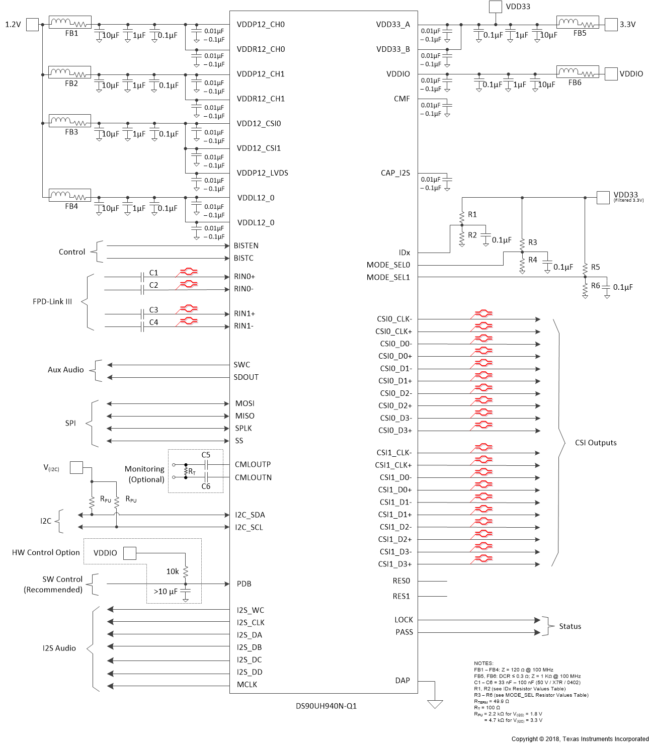
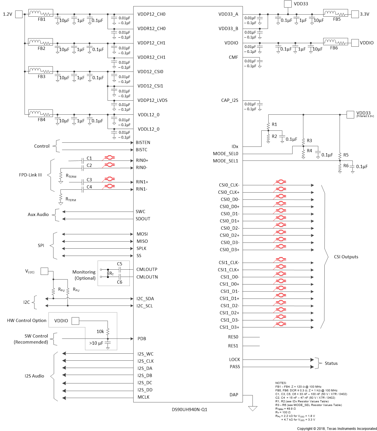
Bypass capacitors must be placed near the power supply pins. At a minimum, use four (4) 10-µF capacitors for local device bypassing. Ferrite beads are placed on the two sets of supply pins (VDD33 and VDDIO ) for effective noise suppression. The interface to the graphics source is LVDS. The VDDIO pins may be connected to 3.3 V or 1.8 V. A capacitor and resistor are placed on the PDB pin to delay the enabling of the device until power is stable. See Figure 38 for a typical STP connection diagram and Figure 39 for a typical coax connection diagram.
 Figure 38. Typical Connection Diagram (STP)
  Figure 39. Typical Connection Diagram (Coax)
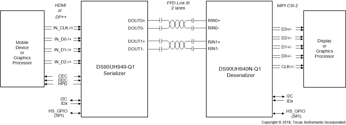
  Figure 40. Typical Display System Diagram