ZHCSGP4C August 2017 – May 2019 INA1650-Q1 , INA1651-Q1
PRODUCTION DATA.
7.3.2 Supply Divider
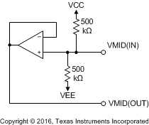
The INA165x-Q1 have an integrated supply-divider circuit that biases the input common-mode voltage and output reference voltage to the halfway point between the applied power supply voltages. The nominal output voltage of the supply divider circuit is shown in Equation 2:

Figure 40 illustrates the internal topology of the supply-divider circuit. The supply divider consists of two 500-kΩ resistors connected between the VCC and VEE pins of the INA165x-Q1. The noninverting input of a buffer amplifier is connected to the midpoint of the voltage divider that is formed by the 500-kΩ resistors. The buffer amplifier provides a low-impedance output that is required to bias the REF pins without degrading the CMRR. For dual-supply applications where the supply divider circuit is not used, no connection is required for the VMID(IN) or VMID(OUT) pins.
 Figure 40. Internal Supply Divider Circuit