ZHCSJT2A May 2019 – March 2022 INA190-Q1
PRODUCTION DATA
- 1 特性
- 2 应用
- 3 说明
- 4 Revision History
- 5 Pin Configuration and Functions
- 6 Specifications
- 7 Detailed Description
- 8 Application and Implementation
- 9 Power Supply Recommendations
- 10Layout
- 11Device and Documentation Support
- 12Mechanical, Packaging, and Orderable Information
8.1.1 Basic Connections
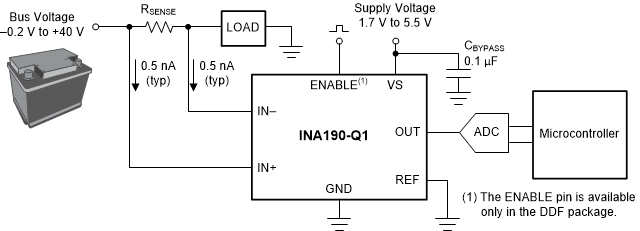
Figure 8-1 shows the basic connections of the INA190-Q1. Place the device as close as possible to the current sense resistor and connect the input pins (IN+ and IN–) to the current sense resistor through kelvin connections.If present, the ENABLE pin must be controlled externally or connected to VS if not used.

NOTE: To help
eliminate ground offset errors between the device and the analog-to-digital
converter (ADC), connect the REF pin to the ADC reference input. When driving
SAR ADCs, filter or buffer the output of the INA190-Q1 before
connecting directly to the ADC.
Figure 8-1 Basic
Connections for the INA190-Q1