SBOS247C June 2002 – November 2015 INA217
PRODUCTION DATA.
- 1 Features
- 2 Applications
- 3 Description
- 4 Revision History
- 5 Pin Configuration and Functions
- 6 Specifications
- 7 Detailed Description
- 8 Application and Implementation
- 9 Power Supply Recommendations
- 10Layout
- 11Device and Documentation Support
- 12Mechanical, Packaging, and Orderable Information
8 Application and Implementation
NOTE
Information in the following applications sections is not part of the TI component specification, and TI does not warrant its accuracy or completeness. TI’s customers are responsible for determining suitability of components for their purposes. Customers should validate and test their design implementation to confirm system functionality.
8.1 Application Information
The INA217 is used in professional audio equipment such as professional microphone preamps, moving-coil transducer amplifiers, differential receivers, and bridge transducer amplifiers.
8.2 Typical Application
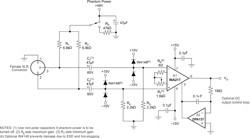
Figure 16 shows a typical circuit for a professional microphone input amplifier.
 Figure 16. Phantom-Powered Microphone Preamplifier
8.2.1 Design Requirements
- 48-V, Phantom powered, remotely located microphone
- Circuitry operates from ±15-V power supplies
- Low distortion and noise over the audio frequency band
- Gain range from to 20 db to 60 db
8.2.2 Detailed Design Procedure
R1 and R2 provide a current path for conventional 48-V phantom power source for a remotely located microphone. An optional switch allows phantom power to be disabled. C1 and C2 block the phantom power voltage from the INA217 input circuitry. Non-polarized capacitors should be used for C1 and C2 if phantom power is to be disabled. For additional input protection against ESD and hot-plugging, four IN4148 diodes may be connected from the input to supply lines.
R4 and R5 provide a path for input bias current of the INA217. Input offset current (typically 100 nA) creates a DC differential input voltage that will produce an output offset voltage. This is generally the dominant source of output offset voltage in this application. With a maximum gain of 1000 (60 dB), the output offset voltage can be several volts. This may be entirely acceptable if the output is AC-coupled into the subsequent stage. An alternate technique is shown in Figure 16. An inexpensive FET-input operational amplifier in a feedback loop drives the DC output voltage to 0 V. A2 is not in the audio signal path and does not affect signal quality.
Gain is set with a variable resistor, R7, in series with R6. R6 determines the maximum gain. The total resistance, R6 + R7, determines the lowest gain. A special reverse-log taper potentiometer for R7 can be used to create a linear change (in dB) with rotation.
8.2.3 Application Curve
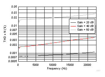
 Figure 17. THD + Noise for the Phantom Powered Microphone Circuit