ZHCSFN7E June 2009 – January 2016 INA220
PRODUCTION DATA.
- 1 特性
- 2 应用范围
- 3 说明
- 4 修订历史记录
- 5 Related Products
- 6 Pin Configuration and Functions
- 7 Specifications
-
8 Detailed Description
- 8.1 Overview
- 8.2 Functional Block Diagram
- 8.3 Feature Description
- 8.4 Device Functional Modes
- 8.5 Programming
- 8.6 Register Maps
-
9 Application and Implementation
- 9.1 Application Information
- 9.2 Typical Application
- 10Power Supply Recommendations
- 11Layout
- 12器件和文档支持
- 13机械、封装和可订购信息
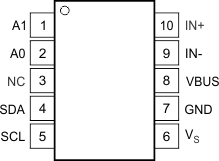
6 Pin Configuration and Functions
DGS Package
10-PIN VSSOP
Top View

Pin Functions
| PIN | I/O | DESCRIPTION | |
|---|---|---|---|
| NAME | NO. | ||
| A1 | 1 | Digital Input | Address pin. Connect to GND, SCL, SDA, or VS. Table 1 shows pin settings and corresponding addresses. |
| A0 | 2 | Digital Input | Address pin. Connect to GND, SCL, SDA, or VS. Table 1 shows pin settings and corresponding addresses. |
| NC | 3 | — | No internal connection |
| SDA | 4 | Digital I/O | Serial bus data line |
| SCL | 5 | Digital Input | Serial bus clock line |
| VS | 6 | Analog | Power supply, 3 V to 5.5 V |
| GND | 7 | Analog | Ground |
| VBUS | 8 | Analog Input | Bus voltage input |
| IN– | 9 | Analog Input | Negative differential shunt voltage. Connect to negative side of shunt resistor. Bus voltage is measured from this pin to ground. |
| IN+ | 10 | Analog Input | Positive differential shunt voltage. Connect to positive side of shunt resistor. |