ZHCSAQ1D February   2013  – July 2022 INA231

PRODUCTION DATA  

  1. 特性
  2. 应用
  3. 说明
  4. Revision History
  5. Device Comparison
  6. Pin Configuration and Functions
  7. Specifications
    1. 7.1 Absolute Maximum Ratings
    2. 7.2 ESD Ratings
    3. 7.3 Recommended Operating Conditions
    4. 7.4 Thermal Information
    5. 7.5 Electrical Characteristics
    6. 7.6 Timing Requirements: I2C Bus
    7. 7.7 Typical Characteristics
  8. Detailed Description
    1. 8.1 Overview
    2. 8.2 Functional Block Diagram
    3. 8.3 Feature Description
      1. 8.3.1 Basic Analog-to-Digital Converter (ADC) Functions
        1. 8.3.1.1 Power Calculation
        2. 8.3.1.2 ALERT Pin
    4. 8.4 Device Functional Modes
      1. 8.4.1 Averaging and Conversion Time Considerations
    5. 8.5 Programming
      1. 8.5.1 Configure, Measure, and Calculate Example
      2. 8.5.2 Programming the Power Measurement Engine
        1. 8.5.2.1 Calibration Register and Scaling
      3. 8.5.3 Simple Current Shunt Monitor Usage (No Programming Necessary)
      4. 8.5.4 Default INA231 Settings
      5. 8.5.5 Writing to and Reading from the INA231
        1. 8.5.5.1 Bus Overview
          1. 8.5.5.1.1 Serial Bus Address
          2. 8.5.5.1.2 Serial Interface
        2. 8.5.5.2 High-Speed I2C Mode
      6. 8.5.6 SMBus Alert Response
    6. 8.6 Register Maps
      1. 8.6.1 Configuration Register (00h, Read/Write)
        1. 8.6.1.1 AVG Bit Settings [11:9]
        2. 8.6.1.2 VBUS CT Bit Settings [8:6]
        3. 8.6.1.3 VSH CT Bit Settings [5:3]
        4. 8.6.1.4 Mode Settings [2:0]
      2. 8.6.2 Shunt Voltage Register (01h, Read-Only)
      3. 8.6.3 Bus Voltage Register (02h, Read-Only)
      4. 8.6.4 Power Register (03h, Read-Only)
      5. 8.6.5 Current Register (04h, Read-Only)
      6. 8.6.6 Calibration Register (05h, Read/Write)
      7. 8.6.7 Mask/Enable Register (06h, Read/Write)
      8. 8.6.8 Alert Limit Register (07h, Read/Write)
  9. Application and Implementation
    1. 9.1 Application Information
      1. 9.1.1 Filtering and Input Considerations
    2. 9.2 Typical Applications
      1. 9.2.1 Design Requirements
      2. 9.2.2 Detailed Design Procedure
      3. 9.2.3 Application Curves
    3. 9.3 Power Supply Recommendations
    4. 9.4 Layout
      1. 9.4.1 Layout Guidelines
      2. 9.4.2 Layout Example
  10. 10Device and Documentation Support
    1. 10.1 Documentation Support
      1. 10.1.1 Related Documentation
    2. 10.2 接收文档更新通知
    3. 10.3 支持资源
    4. 10.4 Trademarks
    5. 10.5 Electrostatic Discharge Caution
    6. 10.6 术语表
  11. 11Mechanical, Packaging, and Orderable Information

封装选项

请参考 PDF 数据表获取器件具体的封装图。

机械数据 (封装 | 引脚)
  • YFF|12
  • YFD|12
散热焊盘机械数据 (封装 | 引脚)
订购信息

说明

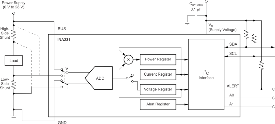
INA231 是一款具有 1.8V I2C 兼容接口(具有 16 个可编程地址)的电流分流和功率监控器。INA231 监控分流压降和总线电源电压,如果数值超出编程范围,其通过将 ALERT 引脚置为有效来提供更好的保护。可编程校准值、转换时间和取平均值与内部乘法器结合使用时,可直接读取电流值(单位为安培)和功率值(单位为瓦特),从而减轻主机处理负载。

INA231 检测总线电压(介于 0V 至 28V 之间)上的电流,该器件由 2.7V 至 5.5V 单电源供电,消耗的电源电流为 330μA‏(典型值)。INA231 额定运行温度范围为 –40°C 至 +125°C。

INA231 有两个版本:INA231A 启动时会执行分流和总线电压的连续转换,而 INA231B 则在低电流关断模式下启动。

封装信息(1)
器件型号封装封装尺寸(标称值)
INA231AYFF (DSBGA-12)1.65mm × 1.39mm × 0.62mm
YFD (DSBGA-12)1.65mm × 1.39mm × 0.40mm
INA231BYFD (DSBGA-12)1.65mm × 1.39mm × 0.40mm
如需了解所有可用封装,请参阅数据表末尾的封装选项附录。
GUID-68037877-9B81-4A5D-87DA-5CFF5023A06F-low.gif高侧或低侧检测