ZHCS793C March 2012 – January 2021 INA282-Q1 , INA283-Q1 , INA284-Q1 , INA285-Q1 , INA286-Q1
PRODUCTION DATA
- 1 特性
- 2 应用
- 3 说明
- 4 Revision History
- 5 Pin Configuration and Functions
- 6 Specifications
- 7 Detailed Description
- 8 Application and Implementation
- 9 Power Supply Recommendations
- 10Layout
- 11Device and Documentation Support
- 12术语表
- 13Mechanical, Packaging, and Orderable Information
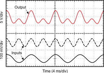
8.2.1.3 Application Curve
Figure 8-3 shows an example output response of a summing configuration. The reference pins of the first circuit are connected to ground, and sine waves at different frequencies are applied to the two circuits to produce a summed output as shown. The sine wave voltage input for the first circuit is offset so that the whole wave is above GND.

| VREF = 0 V | ||