ZHCSEK8A September 2015 – February 2016 INA301
PRODUCTION DATA.
- 1 特性
- 2 应用范围
- 3 说明
- 4 修订历史记录
- 5 Pin Configuration and Functions
- 6 Specifications
- 7 Detailed Description
- 8 Applications and Implementation
- 9 Power Supply Recommendations
- 10Layout
- 11器件和文档支持
- 12机械、封装和可订购信息
8 Applications and Implementation
NOTE
Information in the following applications sections is not part of the TI component specification, and TI does not warrant its accuracy or completeness. TI’s customers are responsible for determining suitability of components for their purposes. Customers should validate and test their design implementation to confirm system functionality.
8.1 Application Information
The INA301 is designed to enable easy configuration for detecting overcurrent conditions in an application. This device is individually targeted towards unidirectional overcurrent detection of a single threshold. However, this device can also be paired with additional devices and circuitry to create more complex monitoring functional blocks.
8.2 Typical Application
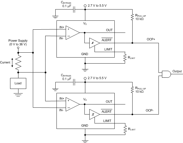
 Figure 42. Bidirectional Application
8.2.1 Design Requirements
Although the device is only able to measure current through a current-sensing resistor flowing in one direction, a second INA301 can be used to create a bidirectional monitor.
8.2.2 Detailed Design Procedure
With the input pins of a second device reversed across the same current-sensing resistor, the second device is now able to detect current flowing in the other direction relative to the first device; see Figure 42. The outputs of each device connect to an AND gate to detect if either of the limit threshold levels are exceeded. As shown in Table 6, the output of the AND gate is high if neither overcurrent limit thresholds are exceeded. A low output state of the AND gate indicates that either the positive overcurrent limit or the negative overcurrent limit are surpassed.
Table 6. Bidirectional Overcurrent Output Status
| OCP STATUS | OUTPUT |
|---|---|
| OCP+ | 0 |
| OCP– | 0 |
| No OCP | 1 |
8.2.3 Application Curve
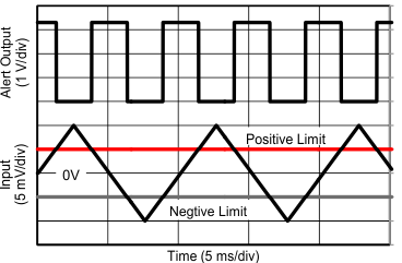
Figure 43 shows two INA301 devices being used in a bidirectional configuration and an output control circuit to detect if one of the two alerts is exceeded.
